Method and system for dynamic creation of service flows

a service flow and dynamic creation technology, applied in the direction of instruments, computing, electric digital data processing, etc., can solve the problems of existing tools not allowing the tool to select and bind to business application systems in real-time, failing to fill gaps, and existing tools not enabling dynamic and real-time development of new web services or collaboration among service providers

Inactive Publication Date: 2006-06-29
IBM CORP
View PDF33 Cites 65 Cited by
  • Summary
  • Abstract
  • Description
  • Claims
  • Application Information

AI Technical Summary

Benefits of technology

[0011] Embodiments in accordance with the invention can enable a method and system for development of new services dynamically in real-time in a more collaborative fashion among service providers. All or portions of a flow for a service can be made visible to other service providers and an indication can be further provided as to which portions of the flow are modifiable by the other service providers. Other service providers can examine the flow and decide to modify the flow by using existing portions of the flow and augmenting the flow with their own additional flow components. A new flow can be created to solve a different business problem while using portions of an originally advertised flow.
[0012] In a first aspect of the invention, a method of dynamic creation of service flows can include the steps of exposing at least a portion of a flow of a service being built to other service providers in a network, soliciting for modification of at least the portion of the flow by other service providers, and selectively enabling modifications of at least the portion of the flow modifiable by other service providers. The method can further include the step of creating a new flow by incorporating the modifications into at least the portion of the flow. The new flow can be created by using at least a portion of the flow and at least a portion of the modifications to the flow. The method can then deploy the new flow as a new service. Optionally, the method can further remove any solicitation for modification once the new flow is created incorporating the modifications. Note, the step of soliciting can include the step of advertising Business Process Execution Language (BPEL) files or tags for the portion of the flow that can be modified by other service providers and can further include the step of tagging the BPEL file to indicate portions of the flow which are available for reuse or modification by the other service providers. Further note that the step of soliciting can also include the step of publishing the BPEL files in a Universal Description, Discovery, and Integration (UDDI)-like directory.

Problems solved by technology

Existing tools fail to enable the dynamic and real-time development of new web services or collaboration among service providers in a real meaningful way.
A business application system that implements a service in a flow might not be known at build-time and existing tools fail to allow the tool to select and bind to business application systems in real-time and fail to fill the gaps in flow nodes where binding to an end-point is not yet completed.
Nor do existing systems provide the knowledge of which portion of flows are modifiable and reusable by other service providers.

Method used


Image

  • Method and system for dynamic creation of service flows
  • Method and system for dynamic creation of service flows
  • Method and system for dynamic creation of service flows

Examples


Embodiment Construction

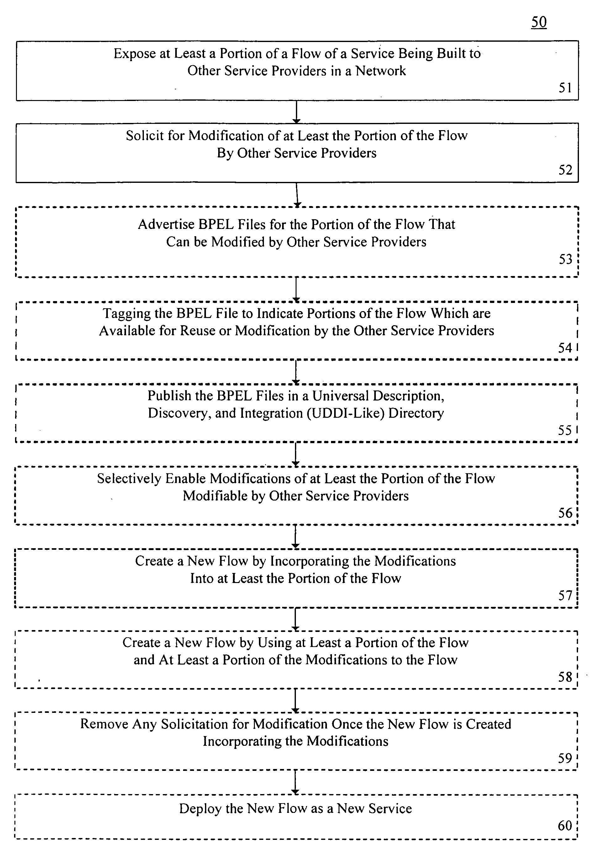
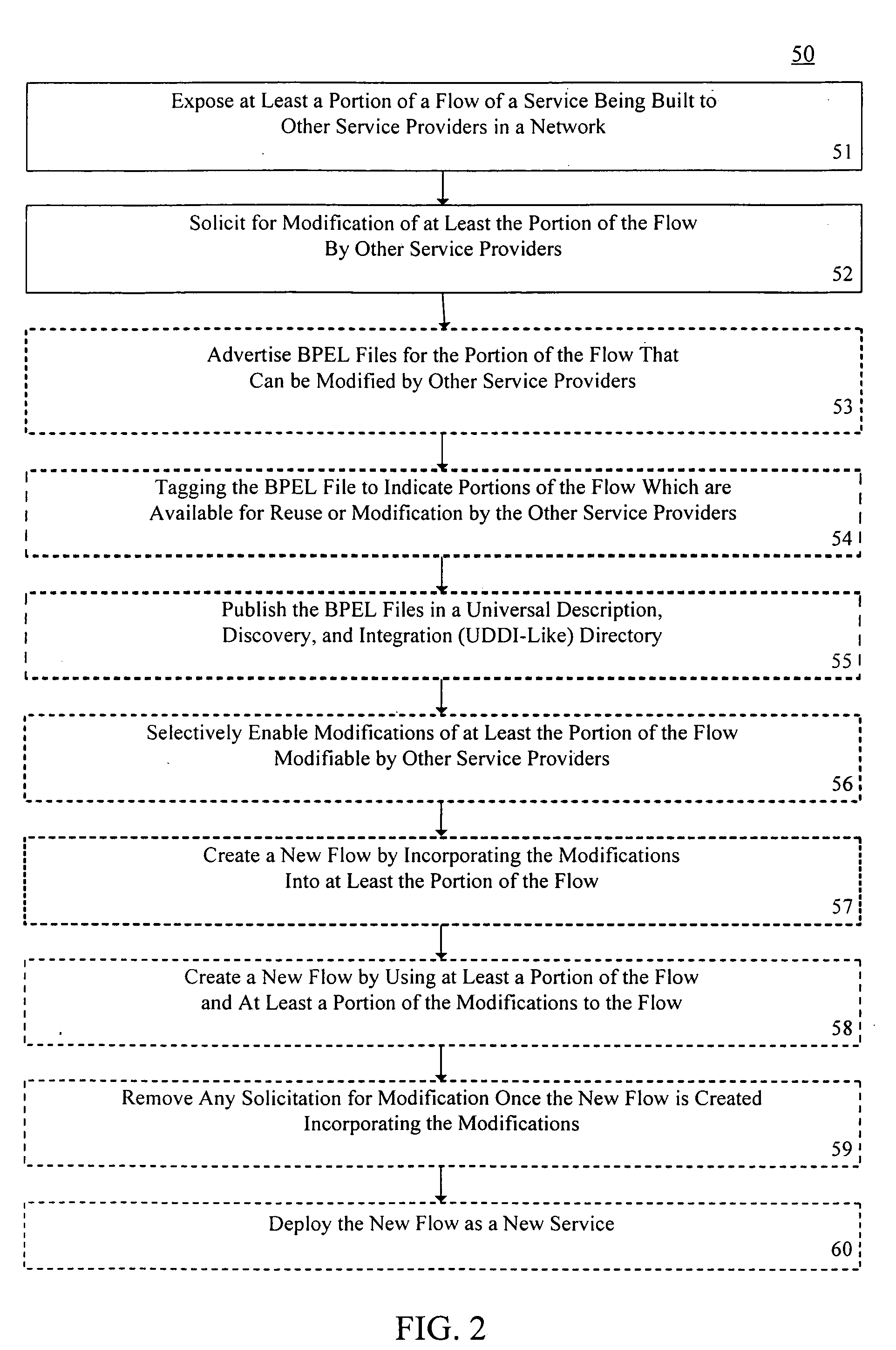
[0018] A flow can be represented in Business Process Execution Language (BPEL) using BPEL tags. A WSDL file describing a Process Service contains BPEL tags or files. BPEL extends WSDL with the introduction of BPEL4WS (Business Process Execution Language for Web Services). Furthermore, the flow composition of a service can be made visible to other service providers. In this regard, a service that implements a process id can be described by a WSDL file to the outside world, but the process portion of the service is described via the BPEL tags. Note, portions or all of the BPEL tags of its WSDL file can be exposed to outside service providers. For example, by making the flow visible, a service provider can advertise the whole flow or parts of it with associated services for use by other service providers. Another service provider that examines the flow can decide to modify the flow by using existing portions of the flow and augment it with their own additional flow components. The new ...


PUM


Abstract

A method (50) of dynamic creation of service flows includes exposing (51) a flow of a service being built to other service providers in a network, soliciting (52) for modification of at least a portion of the flow, and selectively enabling (56) other service providers to modify at least a portion of the flow. The step of soliciting can optionally include advertising (53) BPEL files to indicate flows or portions of flow that are modifiable by other services providers and tagging (54) such BPEL files to indicate such modifiable or reusable portions of the flow. The BPEL files can also be published (55) in a UDDI-like directory. New flows can be created by incorporating (57) the modifications into at least a portion of the flow. Optionally, solicitations for modifications can be removed (59) once the new flow is created.

Description

BACKGROUND OF THE INVENTION [0001] 1. Technical Field [0002] This invention relates to the field of developing service oriented architecture applications, and more particularly to a method and system for dynamically creating web services. [0003] 2. Description of the Related Art [0004] Service Oriented Architecture (SOA) allows a software programmer to model programming solutions in terms of services offered by components to anyone and to anywhere over a network. Services development tools (such as WebSphere Studio Application Developer (WSAD)) are based on the service and process (flow) programming model. The service is the key element in the architecture that binds everything together. The service is implemented by an end-point (a business application), and is described by a Web Services Definition Language (WSDL) file. The process implements a new business service, and makes use of existing services in its implementation. The process implementation can also include other processe...

Claims


Application Information

Patent Timeline
Patent Type & Authority Applications(United States)
IPC IPC(8): G06F17/00
CPCH04L67/16H04L67/20H04L67/14H04L67/53H04L67/51
Inventor BOU-GHANNAM, AKRAM A.CREAMER, THOMAS E.KATZ, NEIL A.MOORE, VICTOR S.
Owner IBM CORP
Why Eureka
Try Eureka