Method for detecting a fault in an HVAC system

a fault detection and hvac system technology, applied in the direction of refrigeration safety arrangement, refrigeration components, electric supply techniques, etc., can solve the problems of reducing the coefficient of performance, the air filter is beginning to clog, and the bypass factor decreases

Inactive Publication Date: 2006-07-06
CARRIER CORP
View PDF11 Cites 57 Cited by
  • Summary
  • Abstract
  • Description
  • Claims
  • Application Information

AI Technical Summary

Benefits of technology

[0008] A vapor compression system operates in a cooling mode to provide cool air to an area. Refrigerant is compressed to a high pressure in a compressor and is cooled in a condenser. The cooled refrigerant is expanded to a low pressure in an expansion device. After expansion, the refrigerant flows through the evaporator and accepts heat from the air, cooling the air that is provided to the area. The refrigerant then returns to the compressor, completing the cycle.

Problems solved by technology

When the air filter is clogged, the bypass factor decreases.
As the error increases, this indicates that the air filter is beginning to clog.
A decrease in the coefficient of performance indicates that the air filter is beginning to clog.

Method used


Image

  • Method for detecting a fault in an HVAC system
  • Method for detecting a fault in an HVAC system
  • Method for detecting a fault in an HVAC system

Examples


Embodiment Construction

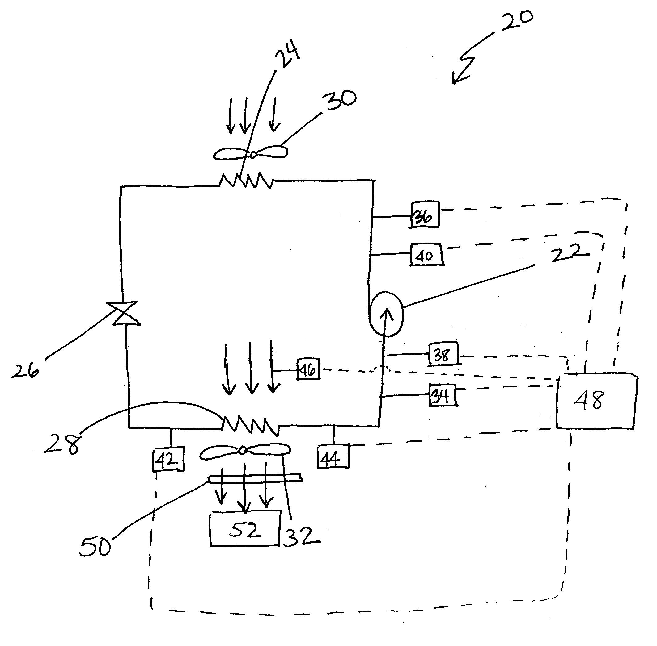
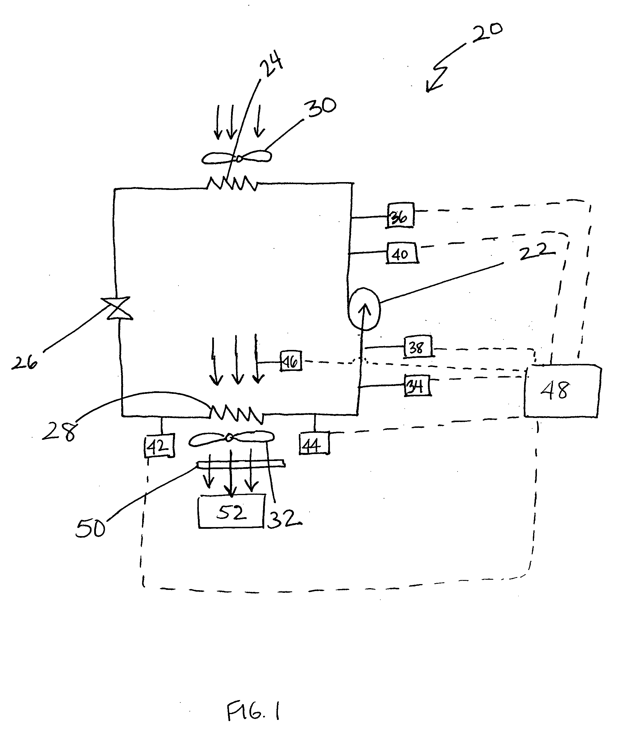
[0018]FIG. 1 illustrates a vapor compression system 20 including a compressor 22, a condenser 24, an expansion device 26, and an evaporator 28. Refrigerant circulates though the closed circuit vapor compression system 20.

[0019] When the vapor compression system 20 is operating in a cooling mode, the refrigerant exits the compressor 22 at a high pressure and a high enthalpy and flows through the condenser 24. In the condenser 24, the refrigerant rejects heat to a fluid medium, such as water or air, and is condensed into a liquid that exits the condenser 24 at a low enthalpy and a high pressure. If the fluid medium is air, a fan 30 is employed to direct the fluid medium over the condenser 24. The cooled refrigerant then passes through the expansion device 26, and the pressure of the refrigerant drops. After expansion, the refrigerant flows through the evaporator 28. In the evaporator 28, the refrigerant accepts heat from air, exiting the evaporator 28 at a high enthalpy and a low pre...


PUM

PropertyMeasurementUnit
pressureaaaaaaaaaa
velocityaaaaaaaaaa
temperatureaaaaaaaaaa

Abstract

A bypass factor of an evaporator is used to indicate when an air filter of an HVAC is clogged. The bypass factor represents the amount of air that is bypassed without direct contact with the evaporator. As the air filter clogs, the bypass factor decreases. The bypass factor can also be used for early detection of clogging of the air filter. A first bypass factor is calculated by using the temperature measurements, and a second bypass factor is calculated by using the airflow rate of the air. The difference between the two bypass factors determines the error. An increase in the error indicates that the air filter is clogged. A coefficient of performance of the evaporator can also be calculated to detect if the air filter is clogged. A decrease in the coefficient of performance indicates that the air filter is clogged.

Description

BACKGROUND OF THE INVENTION [0001] The present invention relates generally to a method for detecting a fault, such as a clogged air filter, in a HVAC system. [0002] A fault in an HVAC system can have a negative effect on the HVAC system. The fault can be a sensor failure, low refrigerant charge, and clogging of an air filter. An air filter is commonly used in an HVAC system to prevent airborne particles from entering an area that is being cooled. Over time, the air filter can clog and must be replaced. If the air filter is clogged, fan power consumption increases and system capacity decreases. [0003] Additionally, the compressor can possibly fail, the life of the equipment can decrease, and the system may have to be taken temporarily out of service. [0004] In prior systems, a sensor is employed to detect when the air filter is clogged. When the sensor detects that the air filter is clogged, an alarm is activated. There are several drawbacks to employing a sensor to detect a clogged ...

Claims


Application Information

Patent Timeline
Patent Type & Authority Applications(United States)
IPC IPC(8): B01D46/00
CPCB01D46/0086B01D46/448F24F2011/0093F25B49/005F25B2500/19F25B2500/04F24F11/39Y10S55/34Y10S116/25
Inventor KANG, PENGJUFARZAD, MOHSENFINN, ALANSADEGH, PAYMAN
Owner CARRIER CORP
Why Eureka
Try Eureka