Built-in type heating cooking device

a built-in type, cooking device technology, applied in the direction of heating types, gaseous heating fuel, stoves or ranges, etc., can solve the problems of difficult to provide both reliable protection against spilled liquids and good cooling performan

Inactive Publication Date: 2006-07-06
PANASONIC CORP
View PDF2 Cites 32 Cited by
  • Summary
  • Abstract
  • Description
  • Claims
  • Application Information

AI Technical Summary

Problems solved by technology

A complicated layout, such as alternately disposed multiple walls, is needed for securing cooling performance.
As a result, the top part cannot be made thin.
In other words, it is difficult to provide both reliable protection against spilled liquids (countermeasures against spilled liquids) and good cooling performance.
More specifically, since the edge is exposed as a component, an extra work of edge treatment needs to be provided, and the area of top pl...

Method used


Image

  • Built-in type heating cooking device
  • Built-in type heating cooking device
  • Built-in type heating cooking device

Examples


first exemplary embodiment

[0059] A first exemplary embodiment is described below with reference to FIGS. 1 to 4.

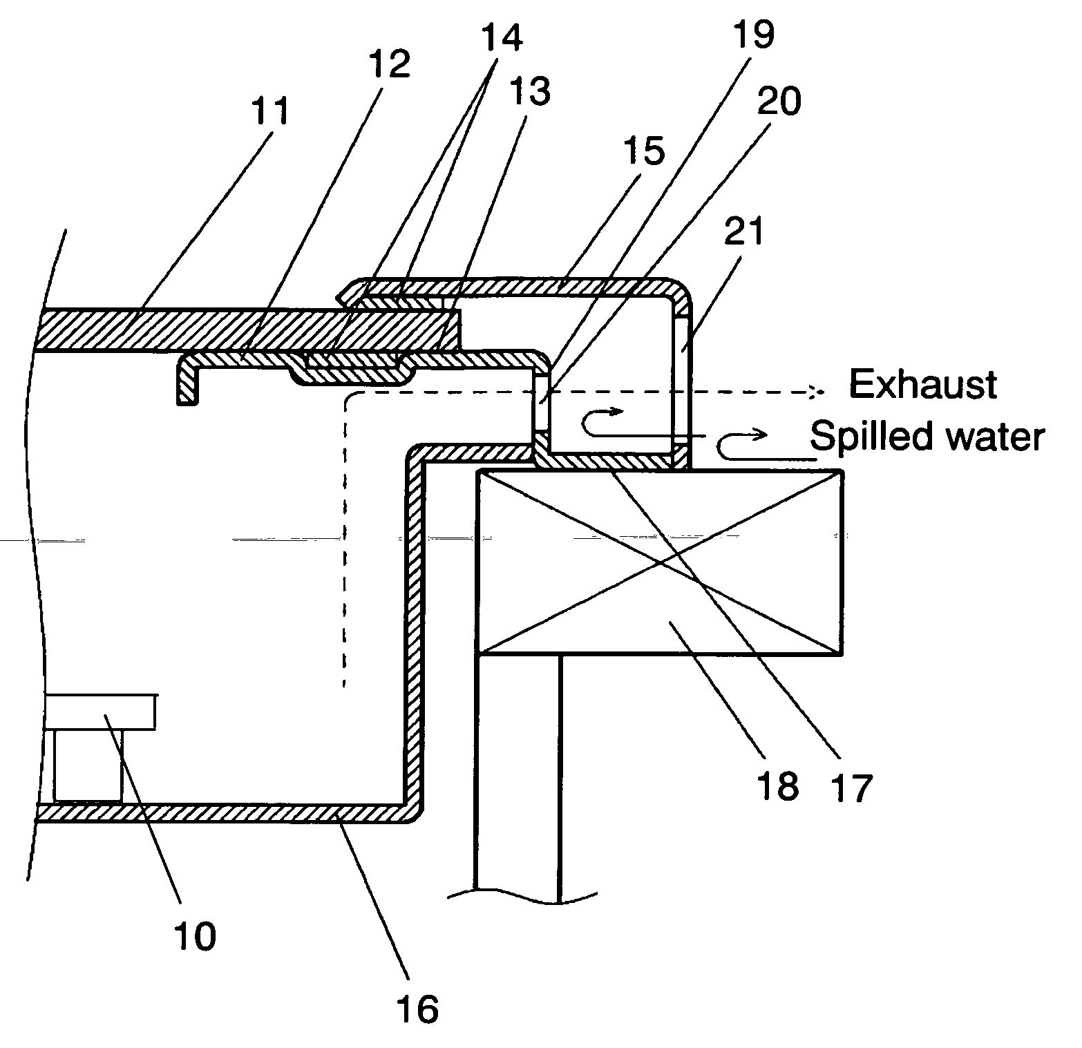
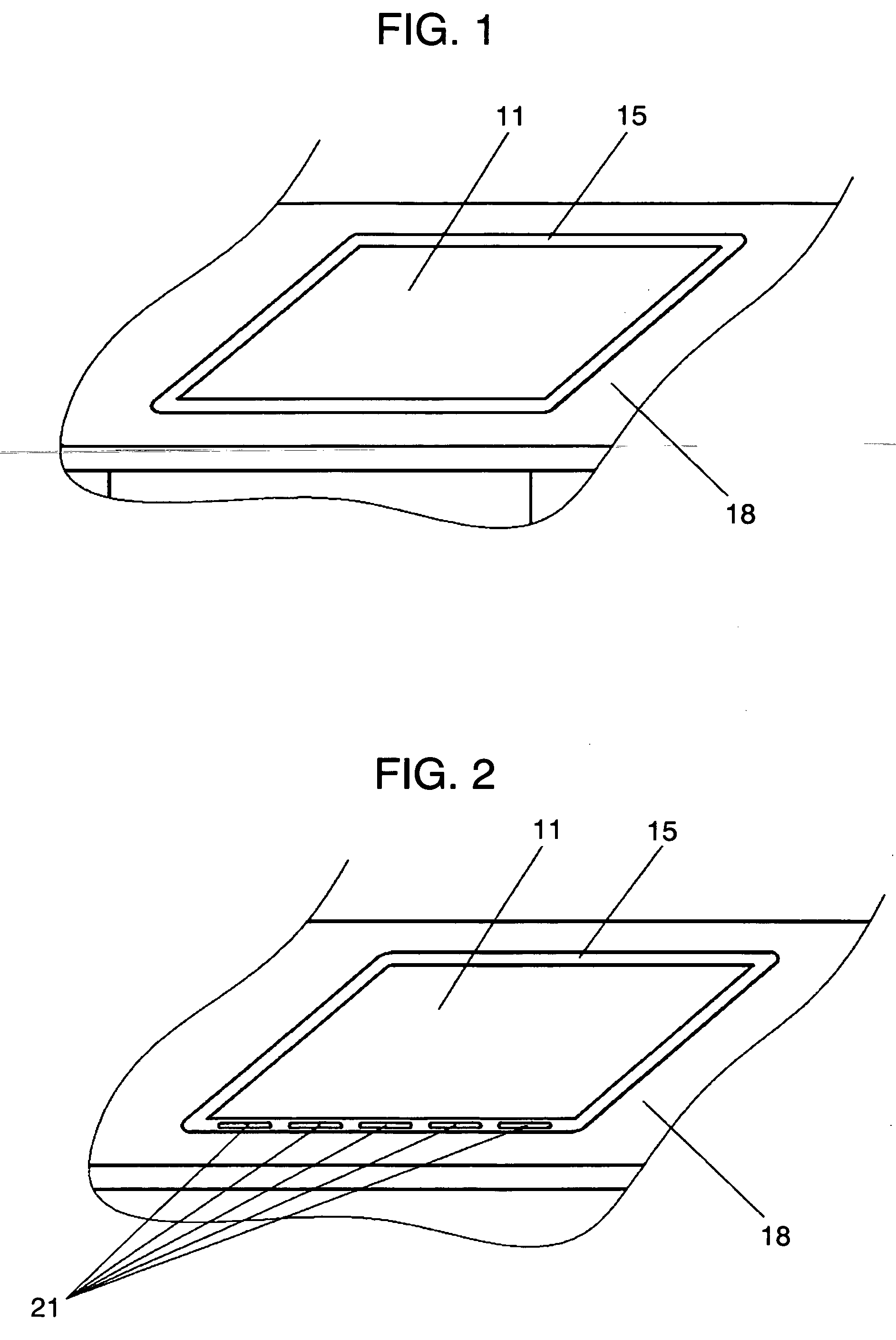
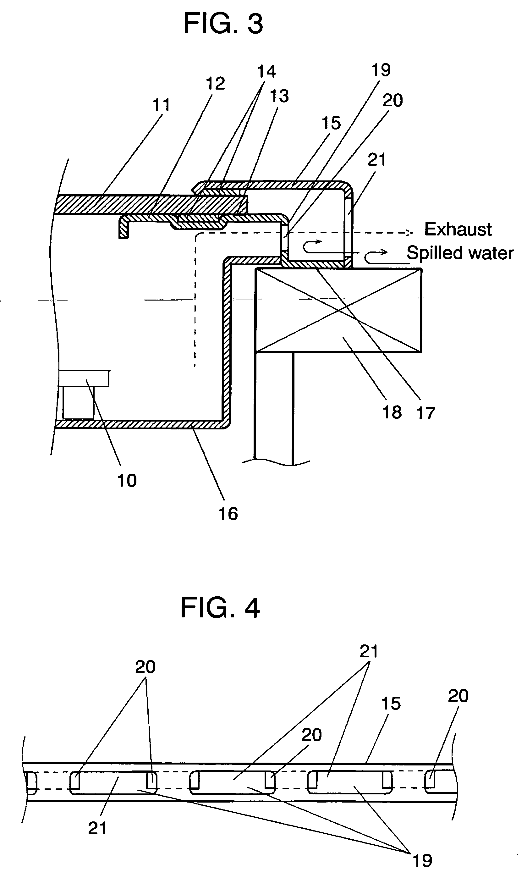
[0060] As shown in FIGS. 1 to 4, top plate 11 where pots are placed is supported from underneath by top plate-supporting face 13 of support 12. Top plate 11 is typically made of a ceramic plate. Top plate 11 and top plate-supporting face 13 are fixed and bonded with heat-resistant adhesive 14. Top frame 15 is provided around the edge of top plate 11 so as to cover its periphery, and top plate11 and top frame 15 are fixed with adhesive 14. Frame 16, constituting the cooker body, is provided inside support 12. Cooker-supporting face 17 is formed outside of top plate-supporting face 13, and the cooker is supported by placing this cooker-supporting face 17 on cabinet 18.

[0061] Side wall 19 is integrally formed between top plate-supporting face 13 and cooker-supporting face 17. Multiple first openings 20 are provided on the surface of side wall 19, configuring a path for letting air in and out to and ...

second exemplary embodiment

[0074] A second exemplary embodiment is described below with reference to FIG. 5.

[0075] As shown in FIG. 5, the basic structure is the same as in the first exemplary embodiment, and thus only the structure different from the first exemplary embodiment is described.

[0076] Flange 22 is provided on the periphery of frame 16. Flange 22 is disposed over cabinet 18.

[0077] Side wall 19 of support 12 is located further inward towards the cooker's internal space than end 23 of flange 22. Flange 22 and frame-supporting face 24, provided between side wall 19 and cooker-supporting face 17, are in contact.

[0078] The operation and function of the ventilation structure of a built-in heating cooker as configured above is described next.

[0079] Also with respect to operation and function, only the parts different from the first exemplary embodiment are described.

[0080] The case of spilling water over top plate 11, and water further entering inside from first openings 20 is examined next. Water ...

third exemplary embodiment

[0083] A third exemplary embodiment is described next with reference to FIG. 6.

[0084] As shown in FIG. 6, the basic structure is the same as the second exemplary embodiment, and thus only the structure different from the second exemplary embodiment is described.

[0085] Side wall 19 is provided underneath top plate 11.

[0086] The operation and effect of the ventilation structure of the cooker as configured above is described next.

[0087] Also for the operation and function, only the parts different from the second exemplary embodiment are described.

[0088] Side wall 19 having first openings 20 is located underneath top plate 11. This enables the securing of space between top plate 11 and flange 22. In other words, the ventilation path can be fully secured. Accordingly, both good cooling performance and countermeasures against spilled liquids are achieved.

[0089] In addition, side wall 19 is disposed under top plate 11. This means that cooker-supporting face 17 can be positioned furt...


PUM


Abstract

A built-in heating cooker which features both good cooling performance and effective countermeasures against spilled liquids by preventing ingress of water into the cooker body with a simple ventilation structure. This built-in cooker comprises a top plate where a pot and the like are placed, a support for supporting the top plate from underneath, a top frame covering the edge of the top plate and a frame constituting the cooker body. The support has a cooker-supporting face for supporting the cooker, and this is positioned outside of the top plate-supporting face. A first opening is provided on at least one side wall provided between the top plate-supporting face and the cooker-supporting face. A second opening is provided on a frame in a position corresponding to the first opening.

Description

TECHNICAL FIELD [0001] The present invention relates to the ventilation structure of built-in heating cookers. BACKGROUND ART [0002] In the ventilation structure of a conventional built-in heating cooker (cooker), an air inlet is typically provided at the front bottom of the cooker and an air outlet is provided at the side rear of the cooker. In addition, a cooker-supporting face is located further in toward the cooker than the air outlet. [0003] The Japanese Patent Laid-open Application No. H11-354263 discloses one of this type of cookers. [0004]FIG. 11 shows the ventilation structure of a conventional cooker. As shown in FIG. 11, top plate 2 configured typically with a ceramic plate is placed and bonded on support 1 constituting the top part of the cooker body. Opening 3 (air outlet) for allowing air from inside the cooker to escape is provided at the side rear of support 1. Cooker-supporting face 4 of support 1 for supporting the cooker itself is formed further inward of the cook...

Claims


Application Information

Patent Timeline
IPC IPC(8): F24C3/00F24C15/10A47B77/08F24C15/08H05B6/12
CPCF24C15/101H05B6/12
Inventor HOSOI, KOICHIOKADA, KAZUICHIKODAMA, SATORU
Owner PANASONIC CORP
Why Eureka
Try Eureka