Video projection control apparatus, video projection control method, program, and video projection apparatus

a control apparatus and video technology, applied in the direction of picture reproducers using projection devices, static indicating devices, instruments, etc., can solve the problem of degrading the resolution of video, and achieve the effect of countermeasure against speckle nois

Active Publication Date: 2021-10-19
SONY SEMICON SOLUTIONS CORP
View PDF7 Cites 0 Cited by
  • Summary
  • Abstract
  • Description
  • Claims
  • Application Information

AI Technical Summary

Benefits of technology

[0014]According to an aspect of the present disclosure, a more effective countermeasure against a speckle noise can be taken.
[0015]The effect described herein is not necessarily limited, and any effect described in the present disclosure may be achieved.

Problems solved by technology

Fine gradations are generated by the generation of the speckle noise and, as a result, the resolution of the video is degraded.

Method used


Image

  • Video projection control apparatus, video projection control method, program, and video projection apparatus
  • Video projection control apparatus, video projection control method, program, and video projection apparatus
  • Video projection control apparatus, video projection control method, program, and video projection apparatus

Examples


first embodiment

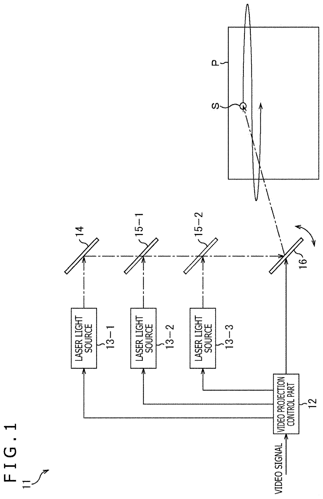
[0033]FIG. 1 is a block diagram depicting an example of the configuration of a video projection apparatus to which the present technique is applied.

[0034]The video projection apparatus 11 depicted in FIG. 1 is a what-is-called laser beam scanning-type projector and includes a video projection control part 12, laser light sources 13-1 to 13-3, a mirror 14, dichroic mirrors 15-1 and 15-2, and a MEMS mirror 16.

[0035]The video projection control part 12 drives the laser light sources 13-1 to 13-3 and the MEMS mirror 16 in accordance with video signal data of input video that is video reproduced by an external reproduction apparatus not depicted and input into the video projection control part 12, and thereby controls projection of the video. For example, the video projection control part 12 controls emission timings of the laser beams of the laser light sources 13-1 to 13-3 such that video in accordance with the video signal data of the input video is projected, and controls a scanning ...

second embodiment

[0100]FIG. 11 is a block diagram depicting an example of a configuration of the video projection apparatus to which the present technique is applied.

[0101]As depicted in FIG. 11, a video projection apparatus 11A is a what-is-called laser beam illumination-type projector, and includes a video projection control part 12A, a laser light source 13, a diffusing lens 31, a modulation element 32, and a projecting lens 33.

[0102]The video projection control part 12A controls the emission intensity of the laser beam output from the laser light source 13 in accordance with the brightness of the input video that is video reproduced by an external reproduction apparatus not depicted and input into the video projection control part 12A, and controls the driving of the modulation element 32 for each pixel in accordance with the input video.

[0103]The laser light source 13 outputs a laser beam that is, for example, a white laser beam having the light beams of all the wavelength regions mixed therein...

third embodiment

[0119]FIG. 13 is a block diagram depicting an example of a configuration of the video projection apparatus to which the present technique is applied.

[0120]As depicted in FIG. 13, a video projection apparatus 11B is a what-is-called laser light source display and includes a video projection control part 12B, laser light sources 13(1) to 13(n), a diffusing lens 51, a liquid crystal panel 52, and a color filter 53.

[0121]The video projection control part 12B controls the emission intensity of the laser beams output from the laser light sources 13(1) to 13(n) in accordance with the brightness of input video that is video reproduced by an external reproduction apparatus not depicted and input thereinto, and controls the driving of each pixel of the liquid crystal panel 52 in accordance with the input video.

[0122]The laser light sources 13(1) to 13(n) output laser beams that are, for example, white laser beams each having the light beams of all the wavelength regions mixed therein, to be u...


PUM


Abstract

The present disclosure relates to a video projection control apparatus, a video projection control method, a program, and a video projection apparatus that enable a more effective countermeasure against a speckle noise. A calculating part calculates projection signal data to project video using a laser beam as a light source, from video signal data, a correcting part applies, to the projection signal data, a correction process of shifting a wavelength of the laser beam for, for example, each frame of the video for projection, and a converting part converts the projection signal data into a driving current supplied to the laser light source. In addition, the laser light source has a property that the wavelength shifts in accordance with an emission intensity employed when the laser light is emitted. The present technique is applicable to, for example, a video projection apparatus that uses a laser beam as its light source.

Description

CROSS REFERENCE TO RELATED APPLICATIONS[0001]This application is a national stage application under 35 U.S.C. 371 and claims the benefit of PCT Application No. PCT / JP2018 / 030491 having an international filing date of 17 Aug. 2018, which designated the United States, which PCT application claimed the benefit of Japanese Patent Application No. 2017-166873 filed 31 Aug. 2017, the entire disclosures of each of which are incorporated herein by reference.TECHNICAL FIELD[0002]The present disclosure relates to a video projection control apparatus, a video projection control method, a program, and a video projection apparatus and, more particularly, to a video projection control apparatus, a video projection control method, a program, and a video projection apparatus that each are enabled to take a more effective countermeasure against a speckle noise.BACKGROUND ART[0003]A laser beam scanning-type projector has conventionally been developed that projects video by causing a laser beam output ...

Claims


Application Information

Patent Timeline
Patent Type & Authority Patents(United States)
IPC IPC(8): H04N9/31G02B26/10G03B21/20
CPCH04N9/3182G02B26/10G03B21/208G03B21/2033H04N9/3135G02B26/0833G02B26/101G02B27/48G03B21/206G09G3/02G09G3/20G09G3/34H04N9/3161H04N9/3164H04N9/3188
Inventor KITAKAMI, YUKINOJONAKAMURA, MASASHI
Owner SONY SEMICON SOLUTIONS CORP
Why Eureka
Try Eureka