Dual fluid cartridge assembly

a fluid cartridge and assembly technology, applied in the direction of liquid transferring devices, instruments, packaged goods types, etc., can solve the problems of unsatisfactory results of dispensed fluids and non-uniform application of fluids

Active Publication Date: 2006-07-06
NORDSON CORP
View PDF31 Cites 15 Cited by
  • Summary
  • Abstract
  • Description
  • Claims
  • Application Information

AI Technical Summary

Benefits of technology

[0007] Briefly, the present invention relates to a dual fluid cartridge assembly adapted to be used with a conventional caulking gun. The dual fluid cartridge assembly includes an inner cartridge, a piston seal and delivery tube, an upper piston seal and an outer cartridge. The outer cartridge is formed with a cartridge outlet for dispensing fluids and is configured to accept conventional mixing nozzles. Fluids are back-filled through the cartridge outlet into the inner cartridge and the outer cartridge fluid chambers. In order to prevent trapped air pockets during the filling of the fluid in the inner cartridge, one or more slots are formed in a base plate of the inner cartridge. These slots extend axially up the sidewall of the inner cartridge a short distance. The axial slots in the inner sidewall of the inner cartridge cooperate with notches formed at the mouth of the inner cartridge and axial elongated slots formed in an inner sidewall of the outer cartridge to provide an air path to atmosphere when the piston tube is in an empty position. As such, as fluid is back-filled into the inner cartridge chamber, the fluid pushes the air into the slots formed in the base of the inner cartridge. As long as the seal portion of the piston seal and delivery tube is engaged with the slots formed in the sidewall of the inner cartridge, air escapes in a direction toward the cartridge outlet and bleeds out the notches at the mouth of the inner cartridge. The elongated axial slots formed in the outer cartridge provide a vent to atmosphere. As the inner cartridge fills up with a fluid, the base of the inner cartridge moves away from the piston past the level of the slots formed in the sidewall, thus closing the vent. Accordingly any air within the inner cartridge and piston tube is vented to the atmosphere during the filling process, thus preventing trapped air pockets within the fluid to provide uniform dispensing of the product. Slots may also be formed in the outer cartridge which are configured to vent air within the outer cartridge to atmosphere.

Problems solved by technology

One problem associated with such dual fluid cartridge assemblies occurs during the fluid filling process.
The inner and outer cartridges are then back-filled with a fluid through the cartridge outlet Unfortunately, this method traps a quantity of air in both the inner and outer cartridge chambers.
The trapped air forms air pockets in the fluid and causes many undesirable affects, such as non-uniform application of the fluids, as well as drooling after the fluid has been dispensed.
In addition, trapped air bubbles in the final mixed product are known to provide unsatisfactory results of the dispensed fluids.

Method used


Image

  • Dual fluid cartridge assembly
  • Dual fluid cartridge assembly
  • Dual fluid cartridge assembly

Examples


Embodiment Construction

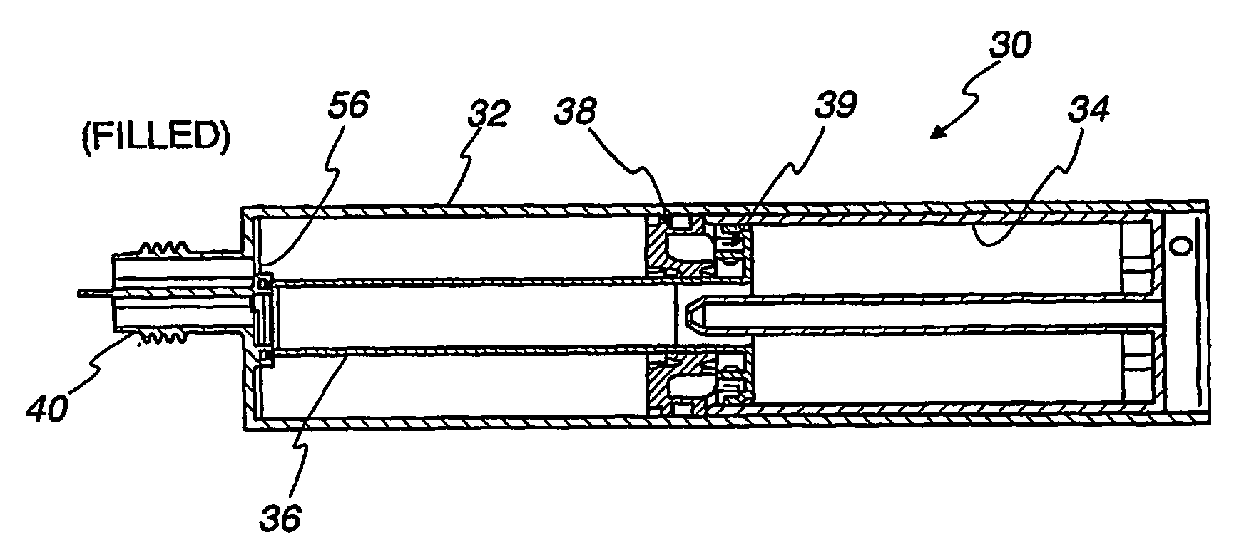
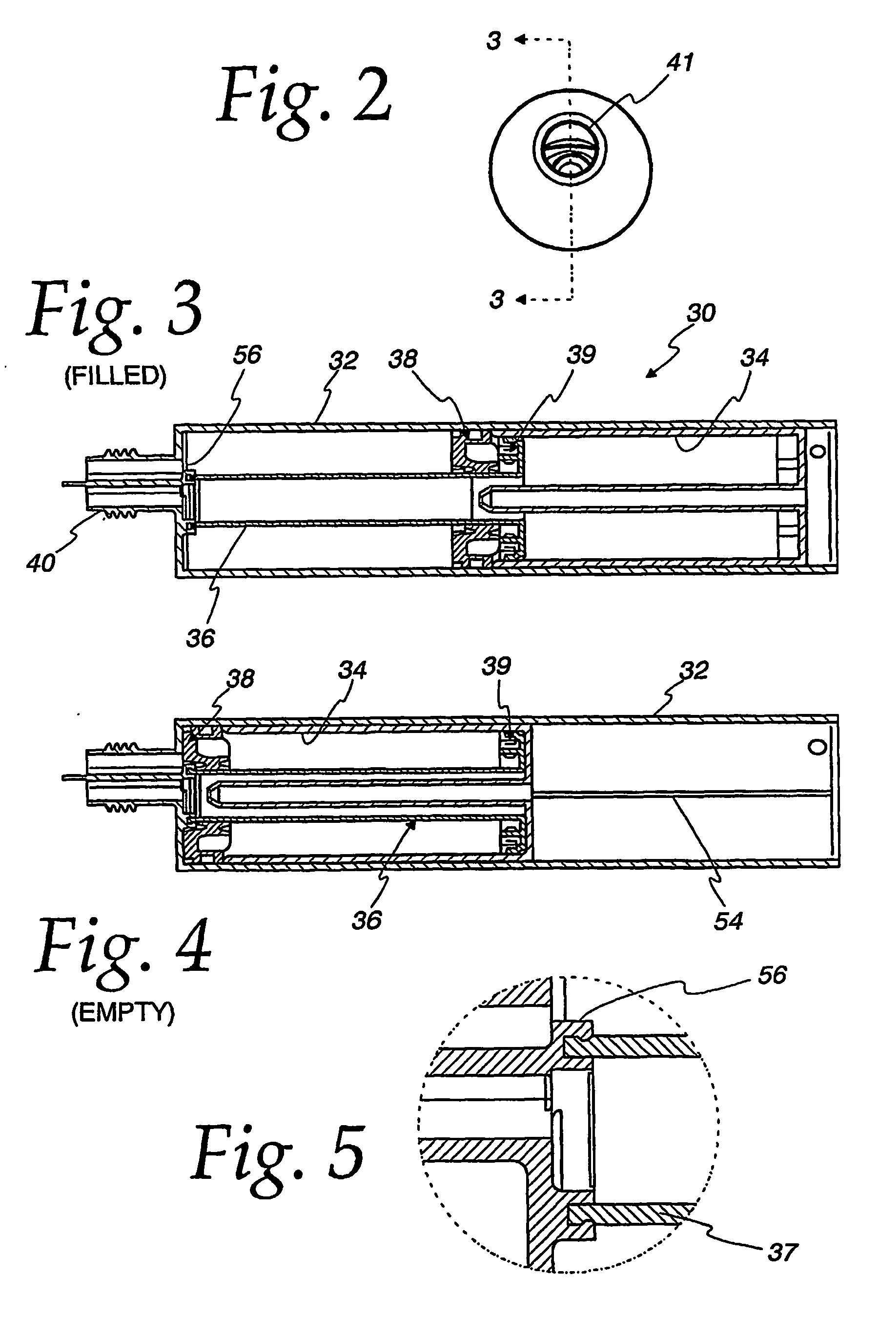
[0029] The present invention relates dual fluid cartridge assembly for carrying two separate fluids, such as a resin and a hardener separately, which is configured to mate with a conventional mixing nozzle to enable the mixed fluids to be applied to a work piece by way of a standard calking gun. Unlike other known dual fluid cartridge assemblies, the dual fluid cartridge assembly in accordance with the present invention is configured with a vent to atmosphere which allows air in the inner cartridge to be evacuated during the fill process in order to prevent any trapped air pockets within the fluid in the inner cartridge in order to provide homogenous mixing of the dual fluids in the assembly. A vent may also be optionally provided in order to vent trapped air from the chamber formed by the outer cartridge as well.

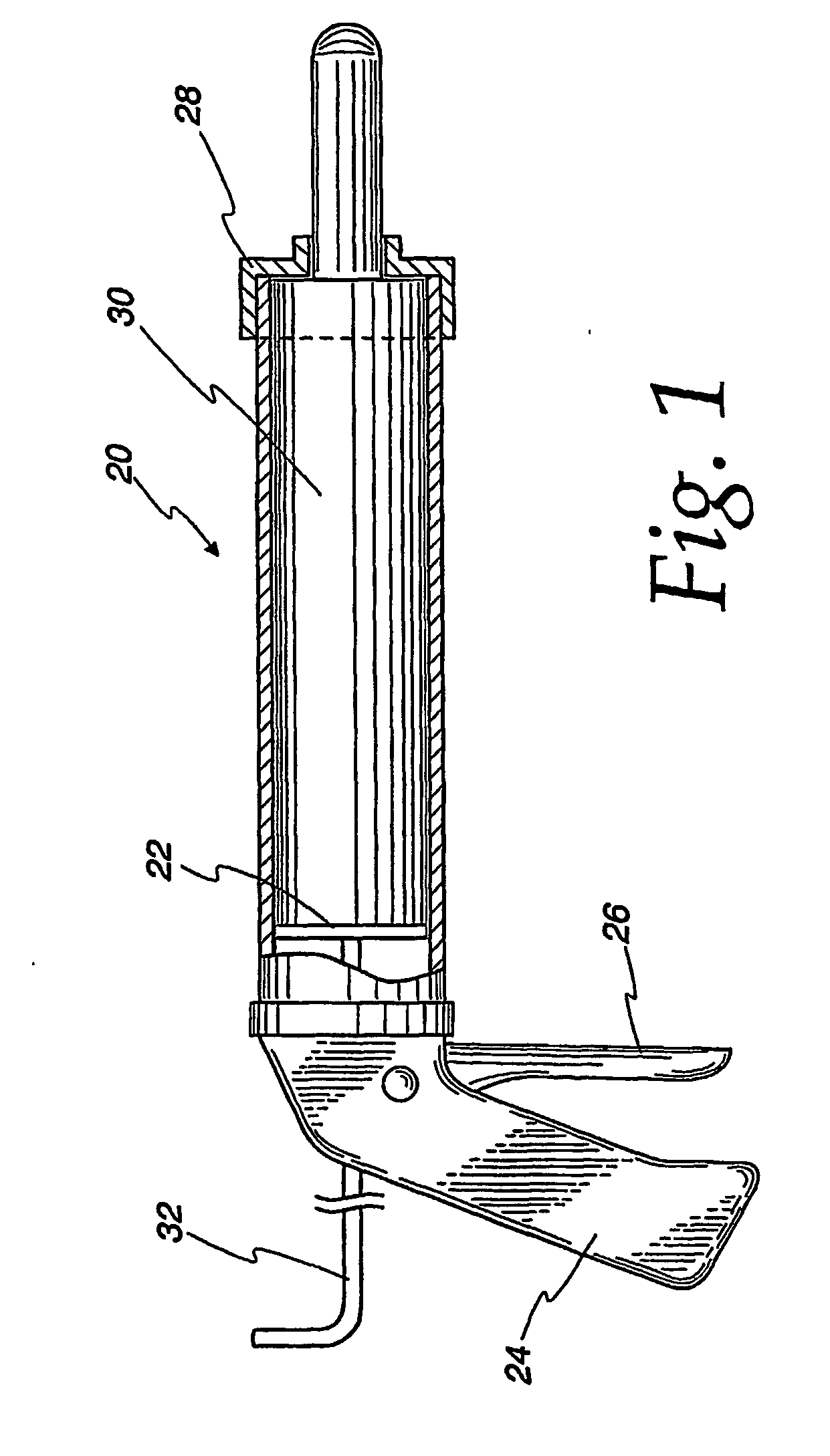
[0030] Referring first to FIG. 1, a dual fluid cartridge assembly in accordance with the present invention is adapted to be dispensed by way of a standard caulking gun 20 ...


PUM

PropertyMeasurementUnit
distanceaaaaaaaaaa
homogenousaaaaaaaaaa
diameteraaaaaaaaaa

Abstract

A dual fluid cartridge assembly (30) is adapted to be used with a conventional caulking gun (20). The dual fluid cartridge assembly includes an outer cartridge (32), a piston seal and delivery tube (36), an upper piston seal (38) and an inner cartridge (34). The outer cartridge includes a cartridge outlet (40) for dispensing fluids and as configured to accept conventional mixing nozzles. Fluids are back-filled through the cartridge outlet into the inner cartridge and the outer cartridges. In order to prevent trapped air pockets during the filling of the fluid in the inner cartridge, one or more slots (54) are formed in a base plate (42) of the inner cartridge.

Description

BACKGROUND OF THE INVENTION [0001] 1. Technical Field [0002] The present invention relates to a dual fluid cartridge assembly and more particularly to a dual fluid cartridge assembly configured with an air vent for evacuating air during filling of the cartridge to eliminate trapped air pockets in the fluid to be dispensed. [0003] 2. Description of the Prior Art [0004] Fluid cartridge assemblies are generally known in the art Both single and multiple fluid cartridge assemblies are known. An example of a single fluid cartridge assembly is disclosed in commonly owned international patent application number PCT / US02 / 39041, filed on Dec. 6, 2002. Such a single fluid cartridge assembly is used to dispense a single fluid. [0005] Dual fluid cartridge assemblies are also known. Examples of such dual fluid cartridge assemblies are disclosed in U.S. Pat. Nos. 4,220,261; 4,961,520; and 5,310,091. Such dual fluid cartridge assemblies are known to be used to dispense fluid materials, such as ther...

Claims


Application Information

Patent Timeline
Patent Type & Authority Applications(United States)
IPC IPC(8): B67D5/52B67D7/70B65B3/12B65D81/32
CPCB05C17/00553B05C17/00559B05C17/01B65B3/12B65D81/325B65D2205/04
Inventor BRENNAN, ROBERT C.SPRINGHORN, ROBERT W.
Owner NORDSON CORP
Why Eureka
Try Eureka