
Key fob with detent mechanism

a key fob and mechanism technology, applied in the field of key fobs, can solve the problems of inadvertent dropping, knocking, hitting the key fob against hard objects and the key fob is subject to continuous physical shock over time, and the key fob is prone to deformation

Inactive Publication Date: 2006-07-06
LEAR CORP
View PDF9 Cites 23 Cited by
  • Summary
  • Abstract
  • Description
  • Claims
  • Application Information

AI Technical Summary

Benefits of technology

This patent is about a key fob with a moveable cap. The key fob has a main body with a button that controls a component for wireless communication with a vehicle system. The main body also has a detent mechanism. The key fob also has a cap that can be opened and closed to access the button. The cap has its own detent mechanism that works with the main body's detent mechanism to secure the cap in either the closed or open position. The technical effect of this invention is to provide a key fob that allows for easy access to the button while still being secure in both the closed and open positions.

Problems solved by technology

The introduction of moisture either by rain, mist, or inadvertent dropping in water puddles near the vehicle inevitably occurs in common use of the key fobs.
The introduction of foreign particle such as dust, dirt and sand also occurs through common use and over time begins to degrade if not completely hinder the normal operation of the key fob.
In addition, as the key fob is often, if not entirely kept along with the car keys and other house keys, the common use also entails inadvertent dropping, knocking, banging, and hitting of the key fob against hard objects.
This continuous physical shock to the key fob over time begins to degrade if not completely hinder the normal operation of the key fob.

Method used


Image

  • Key fob with detent mechanism
  • Key fob with detent mechanism
  • Key fob with detent mechanism

Examples


Embodiment Construction

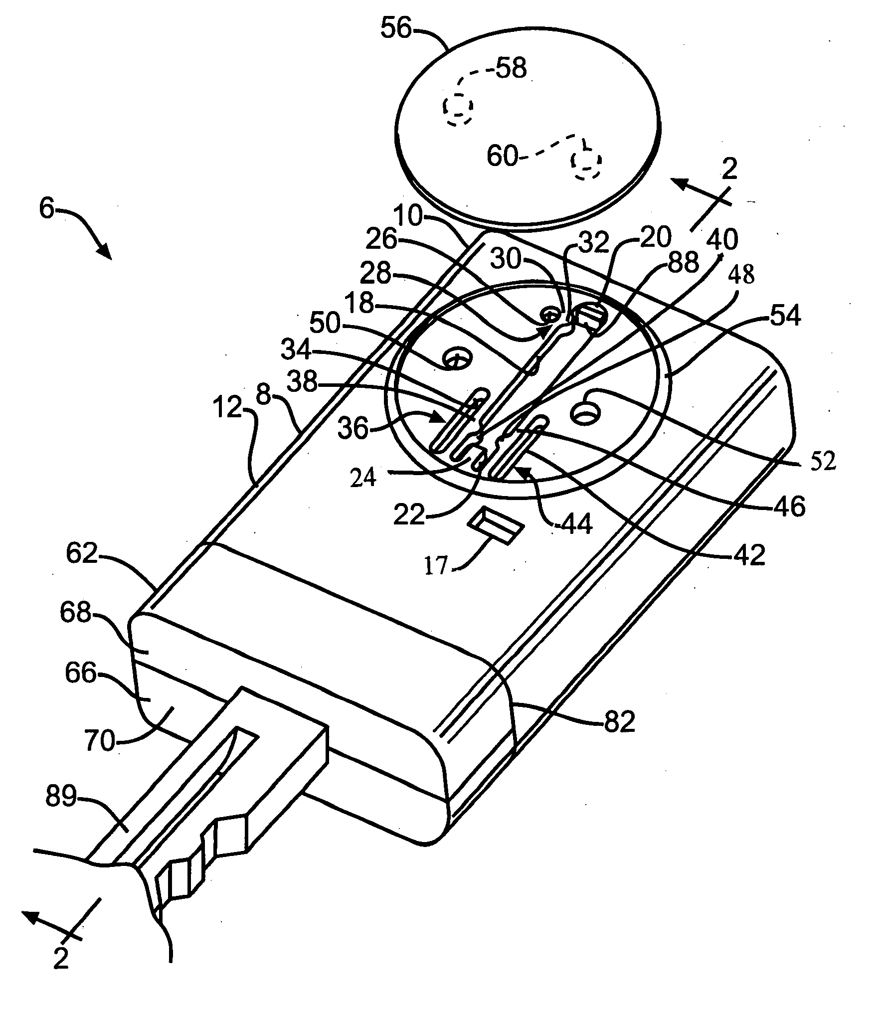
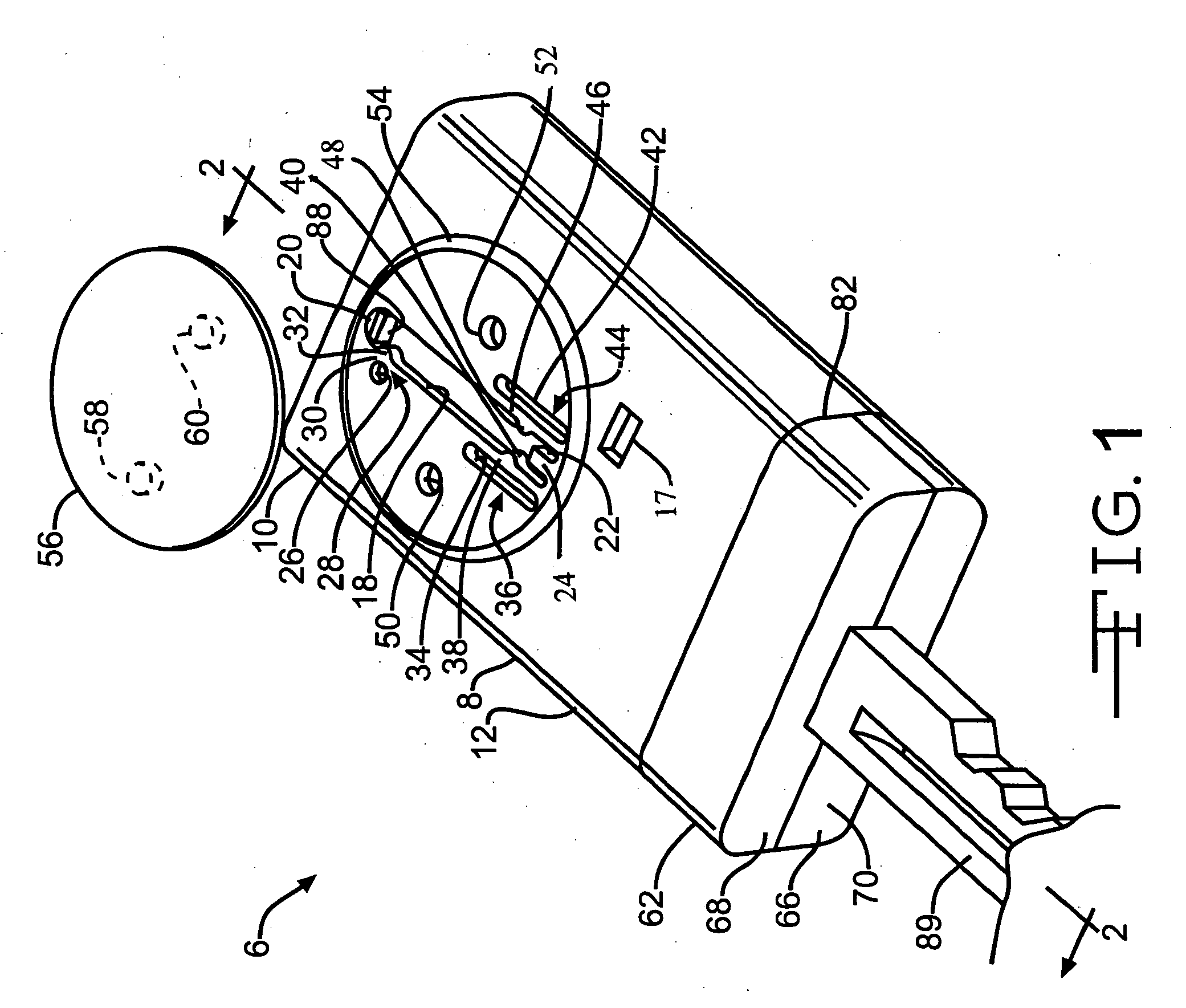
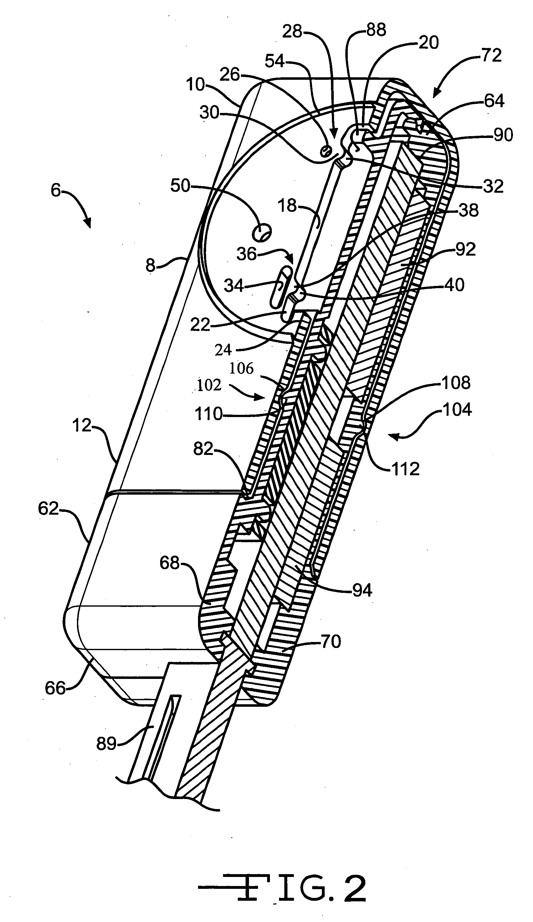
[0012] Referring now to the drawings, there is illustrated in FIGS. 1-4, a key fob 6 in accordance with a preferred embodiment of the present invention. The key fob 6 includes a cap 8. The cap 8 has a first end 10 and a second end 12. Generally, the cap 8 forms a cavity that is closed at the first cap end 10 and open at the second cap end 12.

[0013] Preferably, as best shown in FIG. 4, the cap 8 has a pair of longitudinally extending tracks 14 and 16. The tracks 14 and 16 are formed in opposite surfaces of the cavity of the cap 8 and extend from approximately the first cap end 10 to the second cap end 12. The purpose of the tracks 14 and 16 will be explained below.

[0014] The cap 8 includes as optional cap window 17 that extends through the cap 8 and is in communication with the cavity formed therein. The purpose of the cap window 17 will be explained below.

[0015] The cap 8 preferably includes a generally longitudinally extending slot 18. The slot 18 has a first end 20 near the fir...


PUM


Abstract

A key fob for housing at least one electrical component for wireless communication with a vehicular system includes a main body having at least one actuator button. The actuator button is operable to control an electrical component for wireless communication with a vehicular system. The main body includes a first detent mechanism. The key fob further includes a cap moveably connected to the main body. The cap is moveable between a closed position and an open position such that in the closed position the cap at least partially covers the actuator button and such that in the open position the cap at least partially exposes the actuator button. The cap includes a second detent mechanism. The second detent mechanism is operable to cooperate with the first detent mechanism to lock the cap relative to the main body in one of the closed position and the open position.

Description

BACKGROUND OF THE INVENTION [0001] This invention relates to key fobs. [0002] Keyless remote entry has become prevalent in its inclusion in new vehicle accessories. More specifically, the use of key fob type mechanisms which allow for the locking and unlocking of vehicle door lock systems, the opening of truck latch mechanisms and the setting and unsetting of alarm systems have become commonplace in new vehicle accessories. High end, as well as low end, vehicles are including the above noted functions as well as other functions in standard accessory packages. In this manner, the importance of the protection of remote keyless entry key fobs is rising. [0003] As the public begins to rely more on more on these key fobs systems, it becomes imperative to protect and preserve the electrical circuitry of these devices. The introduction of moisture either by rain, mist, or inadvertent dropping in water puddles near the vehicle inevitably occurs in common use of the key fobs. The introductio...

Claims


Application Information

Patent Timeline
Patent Type & Authority Applications(United States)
IPC IPC(8): H04Q1/00G08C19/00
CPCE05B19/04G07C9/00944H01H9/0235H01H9/287E05B77/34H01H9/0242
Inventor BUCCINNA, FRANKBURCA, JOHNDOYLE, STEPHEN M.PAGANO, LEONARD E.
Owner LEAR CORP
Learn More