Key duplicating machine

a duplicating machine and key technology, applied in the field of key duplicating machines, can solve the problems of not being portable, machine portable, bulky and heavy,

Inactive Publication Date: 2006-07-06
JET HARDWARE MFG CORP
View PDF10 Cites 22 Cited by
  • Summary
  • Abstract
  • Description
  • Claims
  • Application Information

AI Technical Summary

Benefits of technology

[0014] The invention provides a portable, mechanically operated, key-duplicating machine that relies on a punch-cutting system that selectively punches out the particular notches or “bittings” of a key blank in response to the details of an adjacent and aligned master key. The duplicating machine for cutting a key blank from the notch-profile of a master key comprises a frame having a cutting end and an alignment end. The frame defines a longitudinal axis. A carriage is included and is movable along the longitudinal axis and defines a transverse axis. A key clamping assembly has a first key clamp for holding the key blank and a second key clamp for holding the master key. The key clamping assembly is selectively slidable along the transverse axis. A cutter assembly is located at the cutting end and includes a punch-type cutter pin that is adapted to selectively cut pre-shaped notches from the held key blank. The cutter pin includes a guide section that aligns with the notch-profile of the held master key. The key clamping assembly is rotatable about the transverse axis and with respect to the carriage so that that mounted keys simultaneously face either the cutting end or the alignment end of the frame.

Problems solved by technology

Typical key duplicating machines operate on 110-volt AC or 12-volt DC current and are sometimes carried in a van or service truck, but are really not considered portable owing to their power requirements.
This either makes the machine portable, but bulky and heavy, owing to the required batteries, or not portable in that line voltage is required.
These devices are not able to cut a key blank using an already cut key as a guide (i.e., a key-duplicator key cutter).
Replacement of this cutting wheel may require tools and time, which would likely make the key-duplicating process inefficient and inconvenient.
Other problems regarding portable code-type key-cutting machines include difficulty and awkwardness in operating the device which typically rely on pistol-style actuation and can require substantial strength to operate.

Method used


Image

  • Key duplicating machine
  • Key duplicating machine
  • Key duplicating machine

Examples


Embodiment Construction

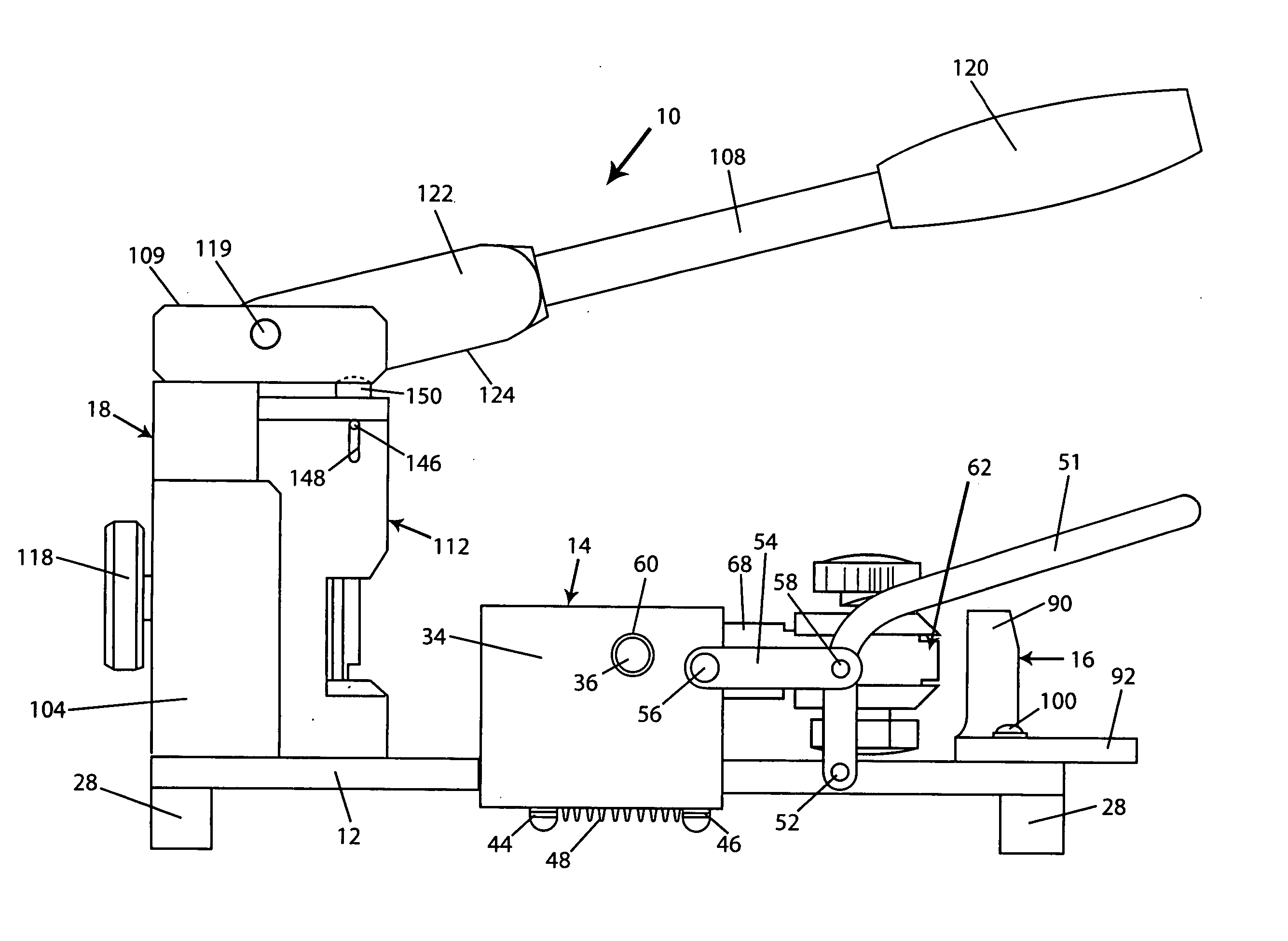
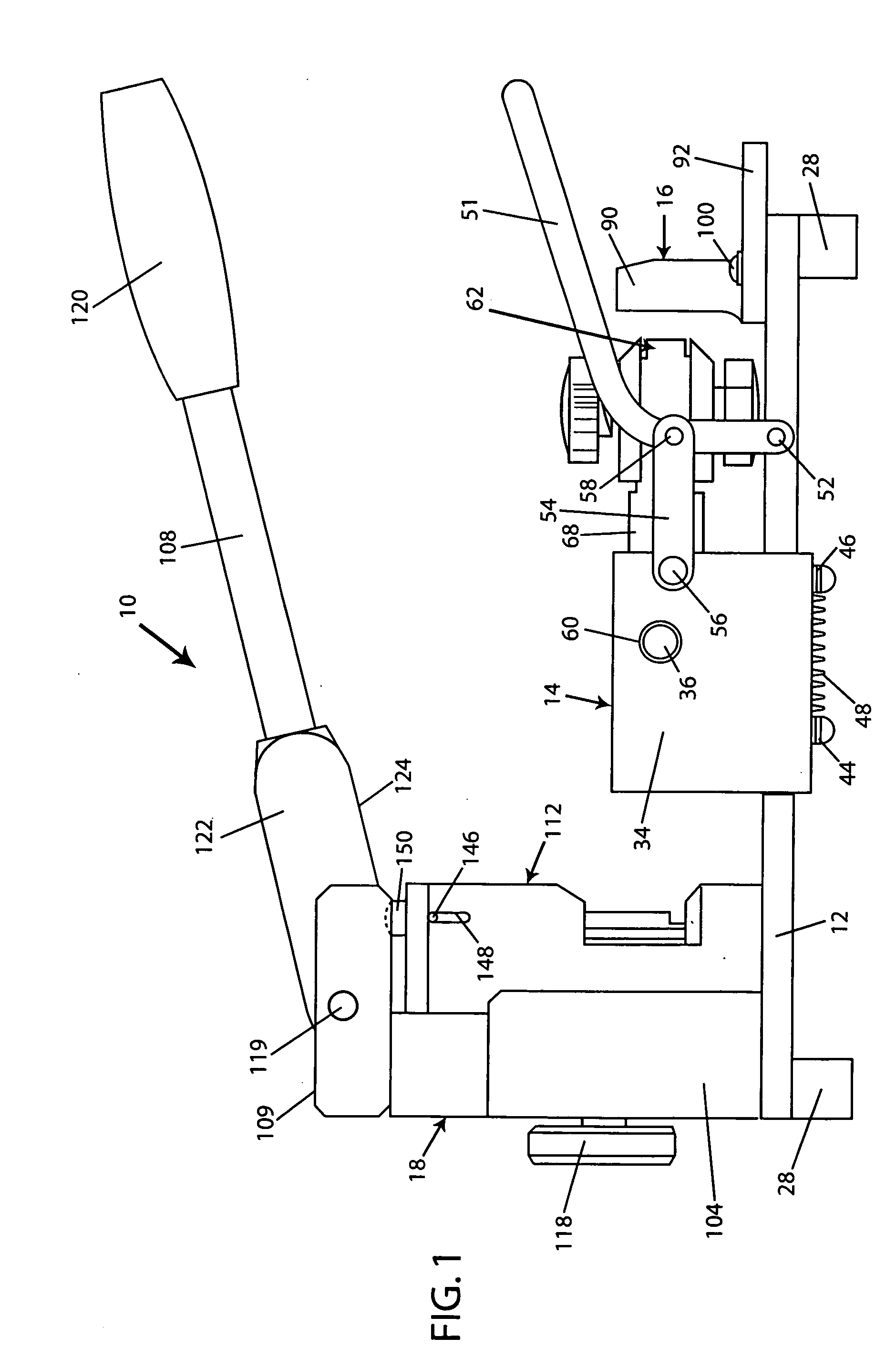
[0029] This invention is a key-duplicating machine that is completely manual in operation and requires no power supply to operate. The machine is quick and easy to use, and can easily cut a key blank following the contours of an already cut key (a key master).

[0030] Referring to FIG. 1, a key-duplicating machine 10 is shown including a flat base plate 12, a slider block 14, a reference set-up block 16, and cutting block assembly 18. The slider block 14 is slidably mounted to base plate 12 between a set-up position and a cutting position, as described in greater detail below.

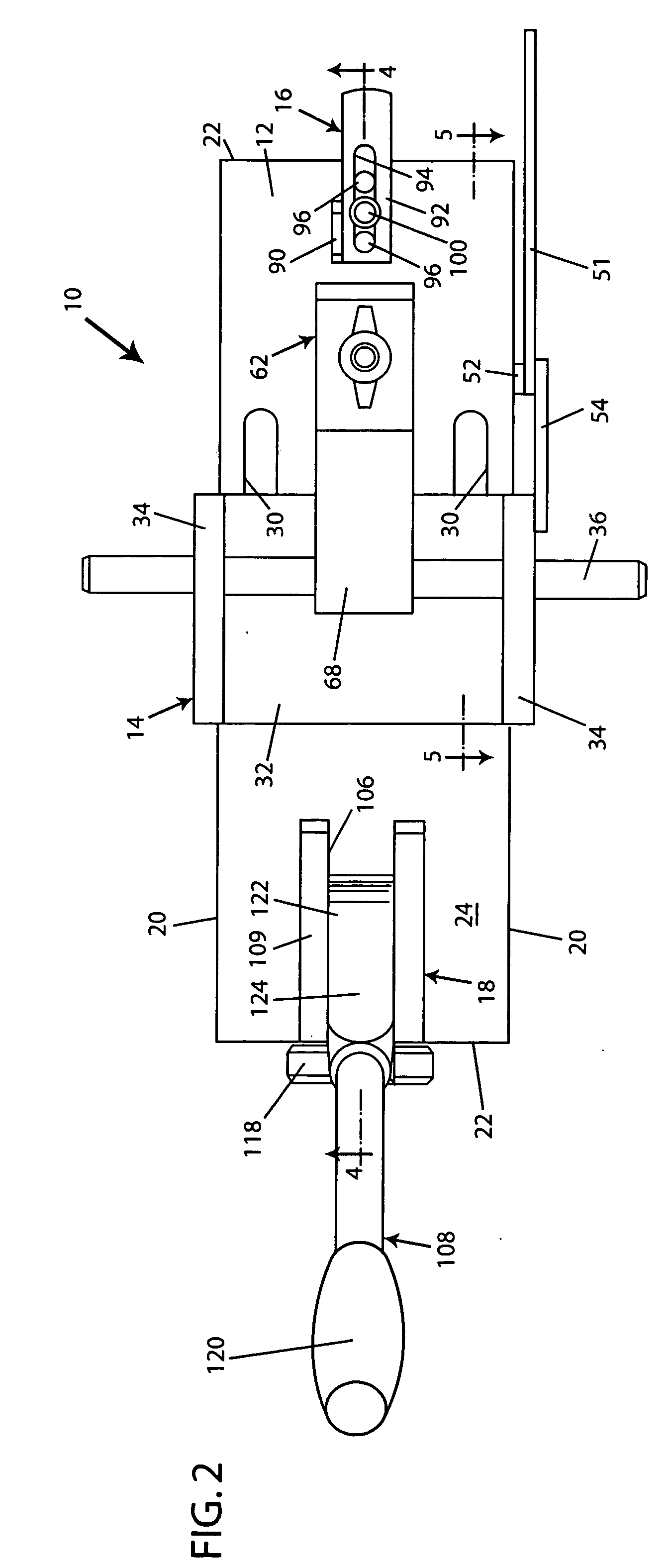
[0031] Referring to FIGS. 2, 4, 5, 6, and 11, base plate 12 is generally rectangular in shape and includes two long sides 20, two relatively shorter ends 22, an upper surface 24, and lower surface 26. Base plate 12 further includes contact feet 28 which are secured to the lower surface 26 of base plate 12, preferably at each corner. Collectively, feet 28 are used to raise the machine 10 above a surface making r...


PUM

PropertyMeasurementUnit
shapeaaaaaaaaaa
angleaaaaaaaaaa
depthaaaaaaaaaa

Abstract

A portable, mechanically operated, key-duplicating machine that relies on a punch-cutting system that selectively punches out the particular notches or “bittings” of a key blank in response to the details of an adjacent and aligned master key. The duplicating machine comprises a frame having cutting end and an alignment end. The frame defines a longitudinal axis. A carriage is movable along the longitudinal axis and includes a transverse axis. A key clamping assembly has a first key clamp for holding the key blank and a second key clamp for holding the master key. The key assembly is selectively slidable along the transverse axis. A cutting assembly is located at the cutting end and includes a punch-type cutter pin that is adapted to selectively cut pre-shaped notches from the held key blank. The cutter pin includes a guide section that aligns with the notch-profile of the held master key. The key clamping assembly is rotatable about the transverse axis and with respect to the carriage so that the mounted keys face either the cutting end or the alignment end of the frame.

Description

BACKGROUND OF THE INVENTION [0001] 1) Field of the Invention [0002] The present invention relates to a key-duplicating machine, and more particularly to an improved key-duplicating machine of the type that uses a punch-type cutter and requires no power supply. [0003] 2) Description of the Prior Art [0004] There are two basic types of key cutting machines—duplicating key-cutting machines and code-cutting key-cutting machines. [0005] A code cutting type machine includes a variety of cutting elements, each of which may be adjusted to control depth, relative position along the key blank, and angle of cut. The adjustment is digitized and follows a specific code, according to the manufacture of the key and lock, the type of lock, the type of key, and the specific shape of the key notches (the key combination). Code books are published listing the longitudinal spacing of the notches along the blade of the key blank and the depth increments of the notches for keys which are utilized to open...

Claims


Application Information

Patent Timeline
Patent Type & Authority Applications(United States)
IPC IPC(8): B23D41/02
CPCB21D53/42Y10T409/40595Y10T409/300952Y10T409/406475
Inventor GIMELFARB, GRIGORYLANG, FREDBUCHINGER, GEORGE
Owner JET HARDWARE MFG CORP
Why Eureka
Try Eureka