
Signal amplifying apparatus and method

a technology of signal amplifying apparatus and signal, which is applied in the field of signal amplifaction, can solve the problems of weakening the strength of the received rf signal, affecting the quality of the signal, so as to achieve efficient amplify of the received signal

Inactive Publication Date: 2006-07-06
SAMSUNG ELECTRONICS CO LTD
View PDF14 Cites 1 Cited by
  • Summary
  • Abstract
  • Description
  • Claims
  • Application Information

AI Technical Summary

Benefits of technology

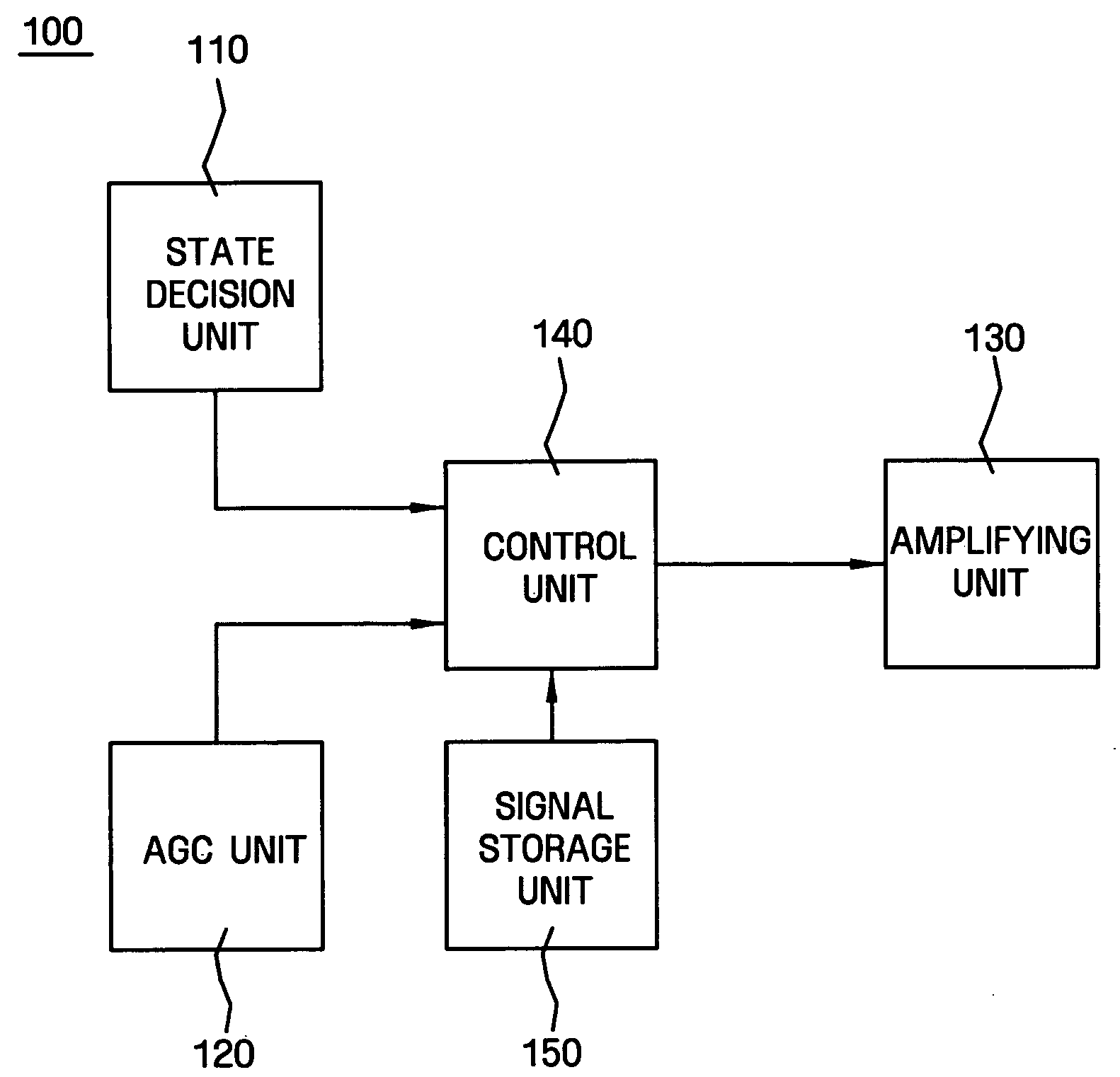
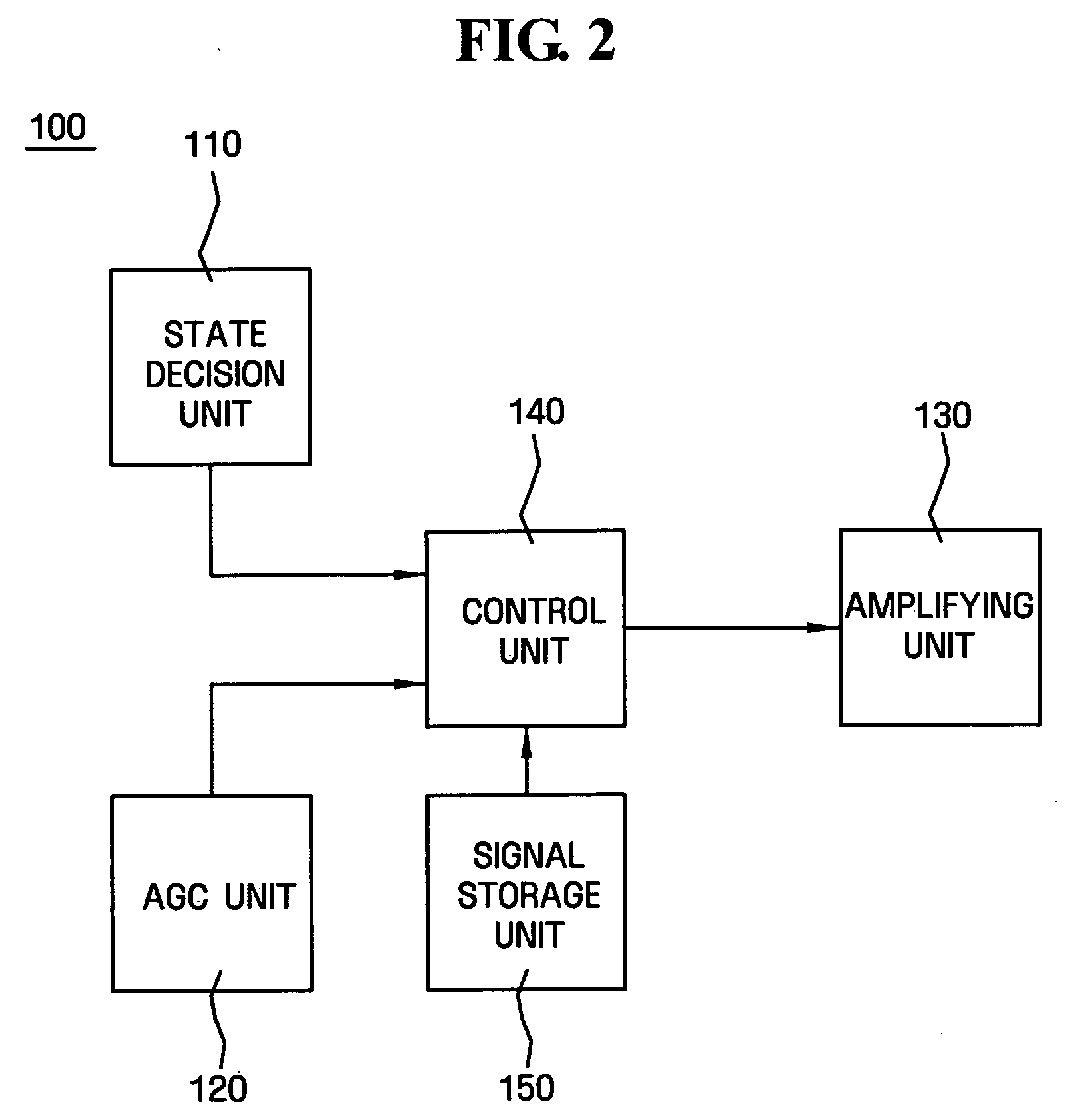
[0014] The present invention provides a signal amplifying apparatus and method which can efficiently amplify a received signal by correcting a reference value according to the environment and determining whether to amplify the received signal according to the corrected reference value.

Problems solved by technology

For example, when an RF signal is received by a television receiver, the strength of the received RF signal is weaker than the original signals due to the influence of neighboring buildings, changes in the air, and other environmental conditions, and the signal is affected by an interference signal.
This interference signal is called a beat, and as the strength of the received RF signal becomes weaker, the RF signal becomes more susceptible to the influence of the beat.
Accordingly, picture interference occurs due to the influence of the beat, and it becomes difficult to obtain a clear picture.
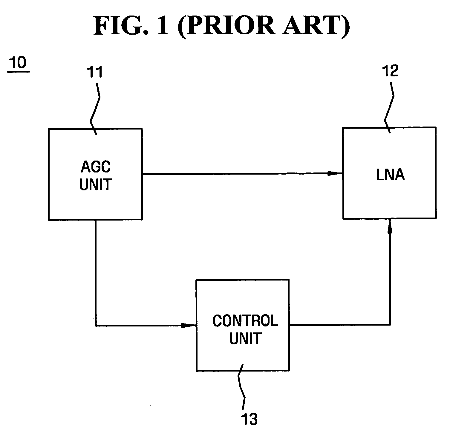
Accordingly, if the environment is changed, an accurate reference value cannot be guaranteed, and thus, the operational reliability of the LNA can decrease.
Although this apparatus and method sets the LNA in an “on / off” state according to the level of the AGC signal after setting the specified reference value, it does not provide any scheme for correcting the reference value according to changes in the environment.

Method used


Image

  • Signal amplifying apparatus and method
  • Signal amplifying apparatus and method
  • Signal amplifying apparatus and method

Examples


Embodiment Construction

[0021] Hereinafter, exemplary embodiments of the present invention will be described in detail with reference to the accompanying drawings. The aspects and features of the present invention and methods for achieving the aspects and features will be apparent by referring to the exemplary embodiments to be described in detail with reference to the accompanying drawings. However, the present invention is not limited to the exemplary embodiments disclosed hereinafter, but will be implemented in diverse forms. The matters defined in the description, such as the detailed construction and elements, are nothing but specific details provided to assist those of ordinary skill in the art in a comprehensive understanding of the invention, and the present invention is only defined within the scope of the appended claims. In the entire description of the present invention, the same drawing reference numerals are used for the same elements across various figures.

[0022]FIG. 2 is a block diagram il...


PUM


Abstract

A signal amplifying apparatus and method selectively amplify a received signal according to the strength of the received signal. The signal amplifying apparatus includes a signal receiving unit for outputting a state signal according to a state of a received radio frequency (RF) signal, an amplifying unit for amplifying the received RF signal and a control unit for determining whether to operate the amplifying unit according to the output state signal.

Description

CROSS-REFERENCE TO RELATED APPLICATION [0001] This application claims priority from Korean Patent Application No. 10-2005-0000466 filed on Jan. 4, 2005, the disclosure of which is incorporated herein in its entirety by reference. BACKGROUND OF THE INVENTION [0002] 1. Field of the Invention [0003] Apparatuses and methods consistent with the present invention relate to signal amplification, and more particularly, to selectively amplifying a received signal according to the strength of the received signal. [0004] 2. Description of the Prior Art [0005] Generally, a television receiver is provided with a low noise amplifier (LNA) installed between an antenna and a tuner in order to heighten the receiving sensitivity. This LNA has a superior noise filtering characteristic. [0006] The strength of a radio frequency (RF) signal received through an antenna changes according to the area and environment. For example, when an RF signal is received by a television receiver, the strength of the re...

Claims


Application Information

Patent Timeline
Patent Type & Authority Applications(United States)
IPC IPC(8): H04B17/00H04B1/06
CPCH03G1/0088H03G3/3052H04B1/109H04N5/52H04N5/44
Inventor KIM, MIN-KYOUNG
Owner SAMSUNG ELECTRONICS CO LTD
Learn More