
Belt for body weight control

a belt and body technology, applied in the field of abdominal compression belts, can solve the problems of reducing the effective stomach capacity, overeating, etc., and achieve the effects of reducing hunger and food intake, reducing hunger, and constant pressure on the stomach

Active Publication Date: 2006-07-06
BRINSTON SR CHARLES LEE
View PDF7 Cites 6 Cited by
  • Summary
  • Abstract
  • Description
  • Claims
  • Application Information

AI Technical Summary

Benefits of technology

The present invention is a weight-reduction belt that can automatically produce a constant pressure on the stomach to reduce hunger and food intake. It can adjust pressure automatically in response to body movements and is programmable to vary pressure against the stomach as desired. It can actively massage the abdomen to reduce hunger and can be used non-invasively, safely, comfortably, and easily to maintain a chronic reduction in weight. It can also be used to supplement other weight loss procedures.

Problems solved by technology

The patent text discusses the problem of obesity in the U.S. and the need for a non-invasive weight reduction belt that can automatically adjust to changes in body position and provide an active massage to the stomach. The current belts are uncomfortable and require manual adjustment. The technical problem is to develop a more effective and comfortable weight reduction belt that can be used in combination with other weight loss procedures.

Method used


Image

  • Belt for body weight control
  • Belt for body weight control
  • Belt for body weight control

Examples


Embodiment Construction

[0023] While the following description details the preferred embodiments of the present invention, it is to be understood that the invention is not limited in its application to the details of construction and arrangement of the parts illustrated in the accompanying drawings, since the invention is capable of other embodiments and of being practiced in various ways.

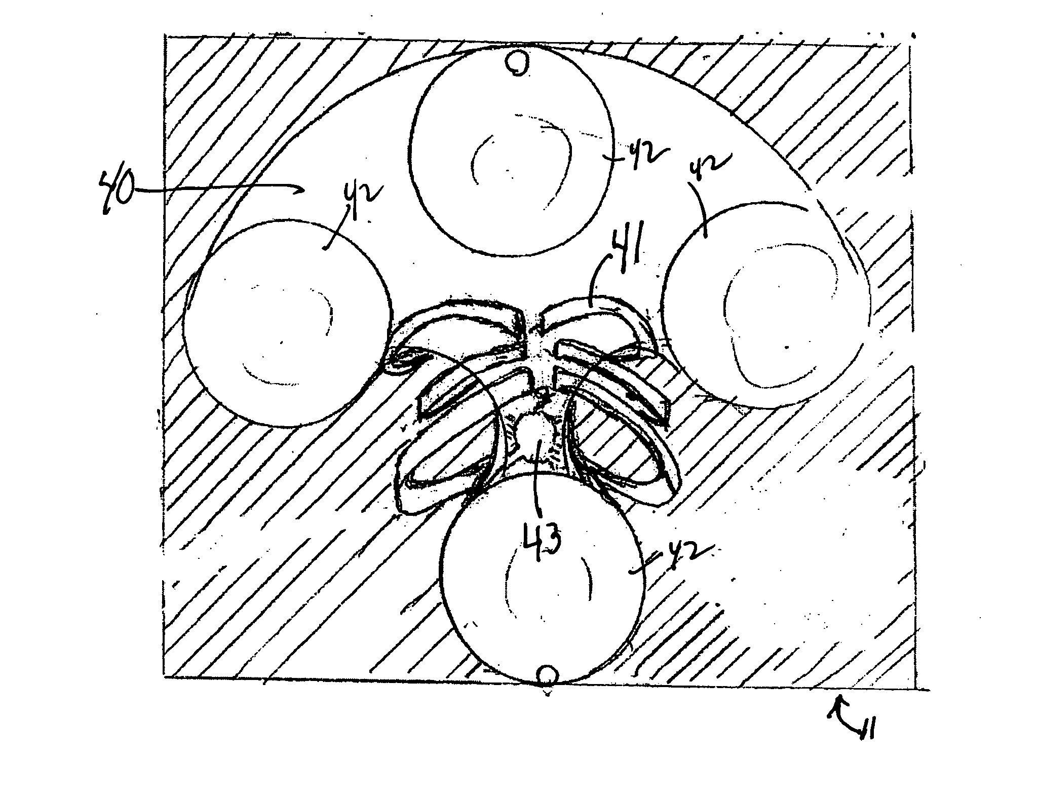
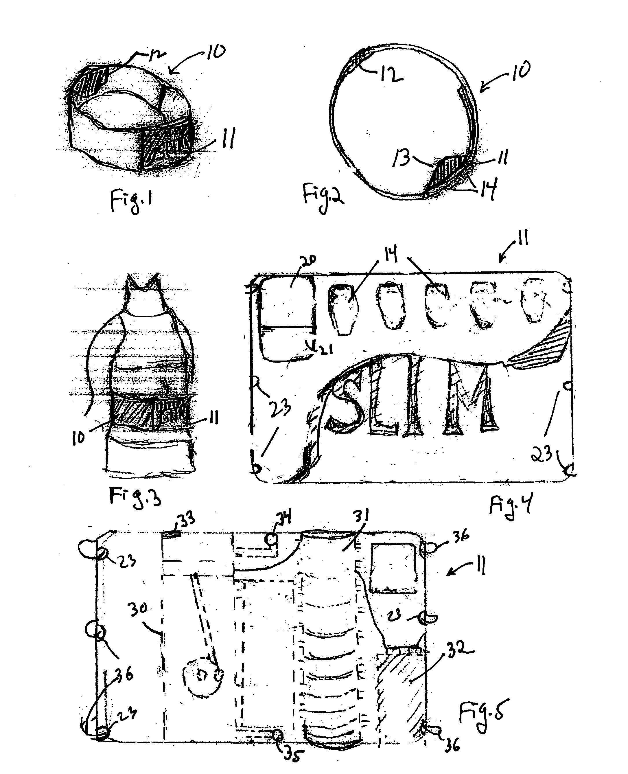
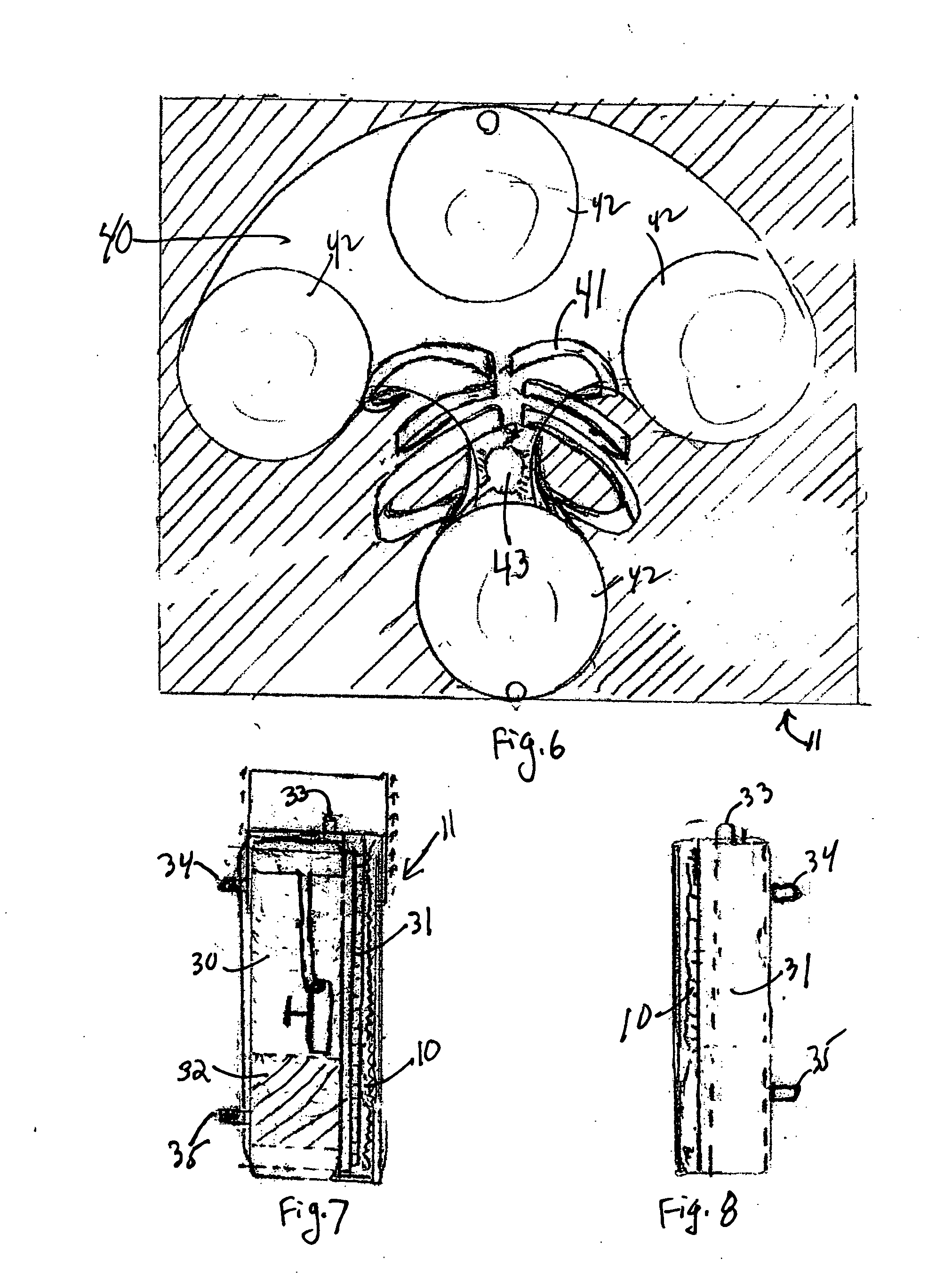
[0024]FIG. 1 shows a perspective view of the weight-reduction belt 10 of the present invention, having a buckle 11 and a back brace 12. FIG. 2 shows a top view of belt 10 further showing the bag 13 that contains the air bladders (see FIG. 6), and buttons 14 on buckle 11 to operate the control system. FIG. 3 shows the weight-reduction belt 10 in place around the waist of a user.

[0025]FIG. 4 shows a front view of buckle 11, further illustrating a forward 20 / reverse 21 button to activate the tension wheel (see FIG. 5) to pull the belt 10 into buckle 11 (tighten) or to push belt 10 out of buckle 11 (loosen). Buckle 11 can h...


PUM


Abstract

A belt for weight reduction having a buckle that fits over the abdomen and stomach, the buckle having one or more air bladders with pressure sensors, an air pump, and a massager. The air bladders are maintained at a constant pressure as signals from the pressure sensors activate the air pump to fill or deflate the air bladder. The constant pressure applied chronically to the abdomen reduces hunger and food intake to produce weight loss. Activation of the massager helps to further control hunger between meals.

Description


Claims


Application Information

Patent Timeline
Owner BRINSTON SR CHARLES LEE
Learn More