Detecting an eye of a user and determining location and blinking state of the user

a technology of eye detection and eye detection, which is applied in the direction of anti-theft devices, process and machine control, instruments, etc., can solve the problems of inability to implement easily in existing vehicles, airbags may be erroneously deployed, and capacitive sensors do not provide accurate positioning information for small occupants

Inactive Publication Date: 2006-07-06
AVAGO TECH WIRELESS IP SINGAPORE PTE
View PDF17 Cites 24 Cited by
  • Summary
  • Abstract
  • Description
  • Claims
  • Application Information

AI Technical Summary

Problems solved by technology

However, because this system does not provide a distinction between tall and short occupants, for example, or occupants who are out of position during a collision, an injury may still result from the explosive impact of the airbag into out-of-position occupants.
Further, the airbag may be erroneously deployed upon sudden deceleration when using the weight sensors to

Method used


Image

  • Detecting an eye of a user and determining location and blinking state of the user
  • Detecting an eye of a user and determining location and blinking state of the user
  • Detecting an eye of a user and determining location and blinking state of the user

Examples


Embodiment Construction

[0019] Reference will now be made in detail to the present embodiments of the present invention, examples of which are illustrated in the accompanying drawings, wherein like reference numerals refer to the like elements throughout. The embodiments are described below to explain the present invention by referring to the figures.

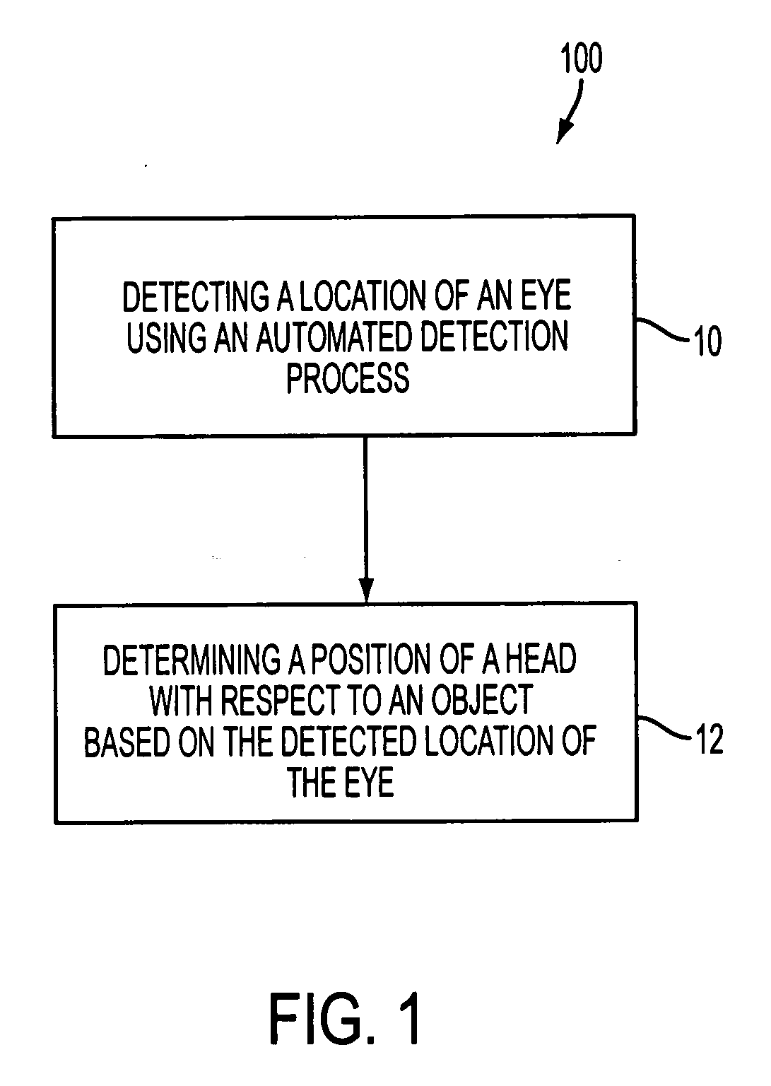
[0020]FIG. 1 is a diagram illustrating a process 100 for detecting a location of an eye using an automated detection process and automatically determining a position of a head with respect to an object based on the detected location of the eye, according to an embodiment of the present invention. Referring to FIG. 1, in operation 10, a location of an eye of a user is detected using an automated detection process. While operation 10 refers to an eye of a user, the present invention is not limited to detecting a single eye of the user. For example, locations of both eyes of a user can be detected using an automated detection process.

[0021] The term “automated”...


PUM


Abstract

A method and apparatus for detecting a location of an eye of a user using an automated detection process, and automatically determining a position of a head of the user with respect to an object based on the detected location of the eye. A location of an eye of a user inside a vehicle is detected using the automated detection process, at least one of height and orientation information of the user is automatically determined based on the detected location of the eye, and a mechanical device inside the vehicle is controlled in accordance with the determined information. Moreover, an eye blinking pattern of a user is detected using an infrared reflectivity of an eye of the user, and messages are transmitted from the user in accordance with the detected eye blinking pattern of the user.

Description

BACKGROUND OF THE INVENTION [0001] 2. Description of the Related Art [0002] Detection of the position of a vehicle occupant is very useful in various industries. One industry that uses such information is the automotive industry where the position of a vehicle occupant is detected with respect to an airbag deployment region to prevent an injury occurring when an airbag deploys due to an automobile crash or other incident. Generally, current solutions rely on a combination of sensors including seat sensors, which detect the pressure or weight of an occupant to determine whether the seat is occupied. However, because this system does not provide a distinction between tall and short occupants, for example, or occupants who are out of position during a collision, an injury may still result from the explosive impact of the airbag into out-of-position occupants. Further, the airbag may be erroneously deployed upon sudden deceleration when using the weight sensors to detect the position of...

Claims


Application Information

Patent Timeline
IPC IPC(8): G06F17/00
CPCB60R25/255
Inventor UNKRICH, MARK A.FOUQUET, JULIE E.HAVEN, RICHARD E.USIKOV, DANIELWENSTRAND, JOHN STEWARTSACHS, TODD STEPHENHORNER, JAMES G.
Owner AVAGO TECH WIRELESS IP SINGAPORE PTE
Why Eureka
Try Eureka