Magnetic read/write head

a magnetic storage system and writer technology, applied in the field of thin film head writers in magnetic storage systems, can solve the problems of occupying considerable real estate, limiting the design of the magnetic via opening, and most solenoidal coil structures are limited to large coil pitch, so as to achieve tight channel-to-channel pitch, improve performance, and reduce the effect of real estate per channel

Inactive Publication Date: 2006-07-13
QUANTUM CORP
View PDF14 Cites 3 Cited by
  • Summary
  • Abstract
  • Description
  • Claims
  • Application Information

AI Technical Summary

Benefits of technology

[0006] Particular implementations of the invention may provide one or more of the following advantages. The solenoidal coil structure with the vertical interconnect structure enables tighter channel-to-channel pitch, lower real estate per channel, a

Problems solved by technology

An upper limit is reached with the single layer pancake coil, which requires turns on the side and at the back of the magnetic via, thus taking up considerable real estate in the writer.
Both pancake designs place a li

Method used


Image

  • Magnetic read/write head
  • Magnetic read/write head
  • Magnetic read/write head

Examples


Embodiment Construction

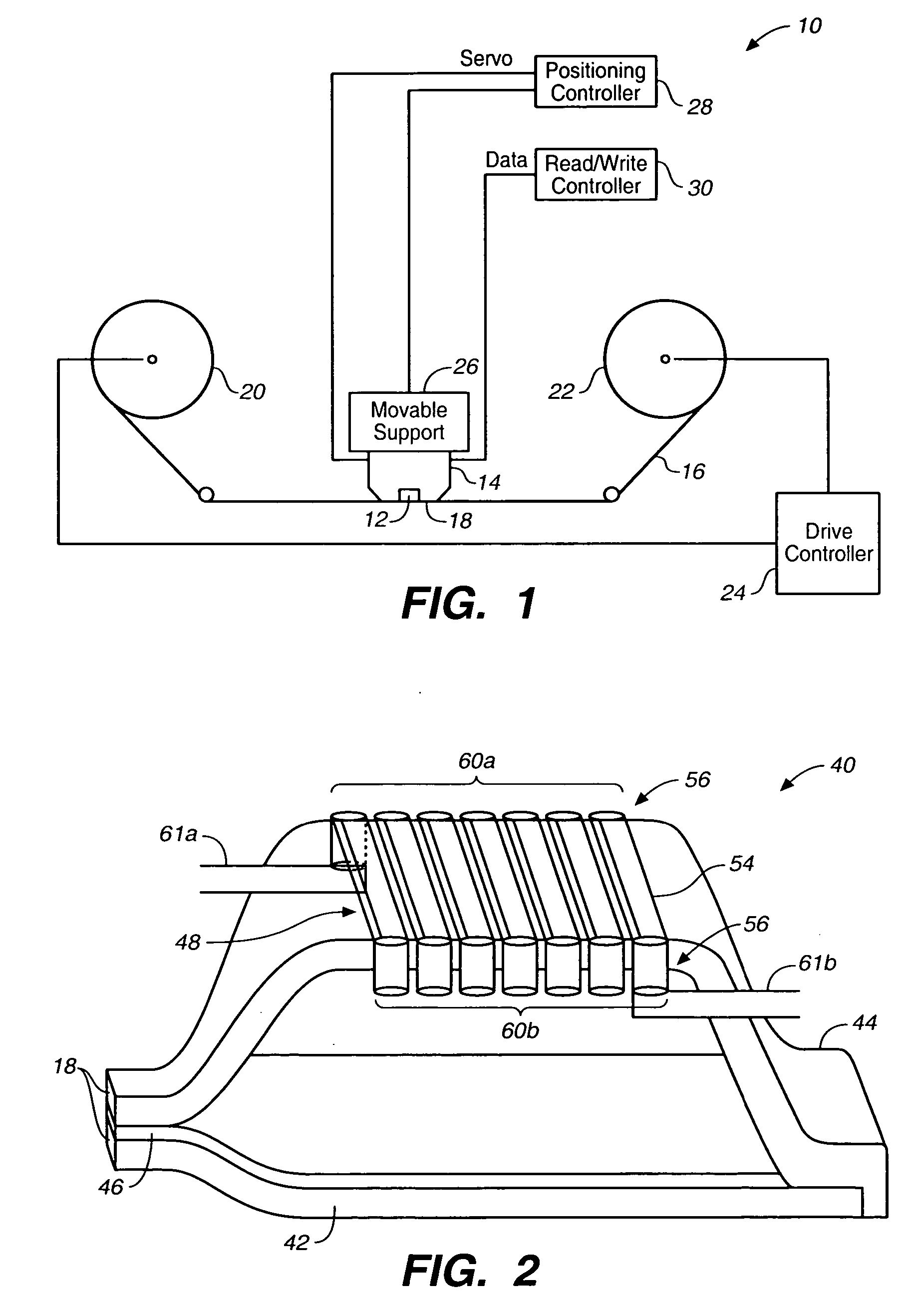
[0027] Referring to FIG. 1, a magnetic tape drive system 10 includes a read / write head 12 that is mounted on a support 14. A magnetic tape 16 is moved linearly past a planar “tape bearing surface” (or “TBS”) 18 of the support 14 and head 12 in either a forward or reverse direction by a pair of reels 20 and 22. A drive controller 24 controls the rotation of the reels 20 and 22 in the forward and reverse directions.

[0028] The support 14 is mounted on a movable support 26, which moves transverse to the magnetic tape 16 so that the head 12 can read and write magnetic information signals on the longitudinally moving tape 16. The head 12 can read servo information on the tape so as to keep the head 12 within a desired track. The head 12 provides the servo information to a position controller 28, which processes the servo information and provides head movement signals to the movable support 26. Further, the head 12 is connected to a read / write controller 30, which processes data read from...


PUM

PropertyMeasurementUnit
Ferromagnetismaaaaaaaaaa

Abstract

A magnetic head for use with a magnetic recording medium includes a top write pole for use in recording information on the magnetic recording medium, and a solenoidal coil structure having a lower coil layer disposed below the top write pole and an upper coil layer disposed above the top write pole. The upper coil layer and the lower coil layer are insulated from the top write pole. The magnetic head also includes a vertical interconnect structure connecting the lower coil layer to the upper coil layer.

Description

CROSS REFERENCE TO RELATED APPLICATIONS [0001] The present application is a divisional of U.S. patent application Ser. No. 10 / 289,120, filed Nov. 5, 2002, which is incorporated by reference in its entirety herein.BACKGROUND OF THE INVENTION [0002] The invention relates generally to thin film head writers in magnetic storage systems. [0003] At present, most thin film writers in merged heads for both disk drive heads and tape drive heads are of the single layer or double layer planar spiral (“pancake”) design. As the need for more channels per head increases, the channel-to-channel pitch decreases, resulting in the need for a more compact coil. An upper limit is reached with the single layer pancake coil, which requires turns on the side and at the back of the magnetic via, thus taking up considerable real estate in the writer. This single layer pancake coil disadvantage is somewhat alleviated by a double layer pancake coil at the expense of fabrication complexity and a more thermally...

Claims


Application Information

Patent Timeline
IPC IPC(8): G11B5/187G11B5/008G11B5/17G11B5/31G11B5/33G11B5/39G11B5/55G11B5/584
CPCG11B5/00813G11B5/17G11B5/313G11B5/332G11B5/3967Y10T29/49021G11B5/584Y10T29/49052Y10T29/49071Y10T29/49039Y10T29/49032G11B5/5504
Inventor BASRA, VIJAY K.NEUMANN, LAWRENCE G.LIU, ZHENGHAO JEFFREY
Owner QUANTUM CORP
Why Eureka
Try Eureka