Rescue sleeve for buildings

Inactive Publication Date: 2006-07-13
CAMPINA BV
View PDF14 Cites 1 Cited by
  • Summary
  • Abstract
  • Description
  • Claims
  • Application Information

AI Technical Summary

Benefits of technology

[0006] Provided according to the invention is a rescue system for evacuating individuals through a window frame of a high-rise building comprising a rescue sleeve foldable between a compact, standby position and an extended, sloping down to ground level

Problems solved by technology

These ladders are of limited capacity in terms of height and evacuation rate.

Method used


Image

  • Rescue sleeve for buildings
  • Rescue sleeve for buildings
  • Rescue sleeve for buildings

Examples


Embodiment Construction

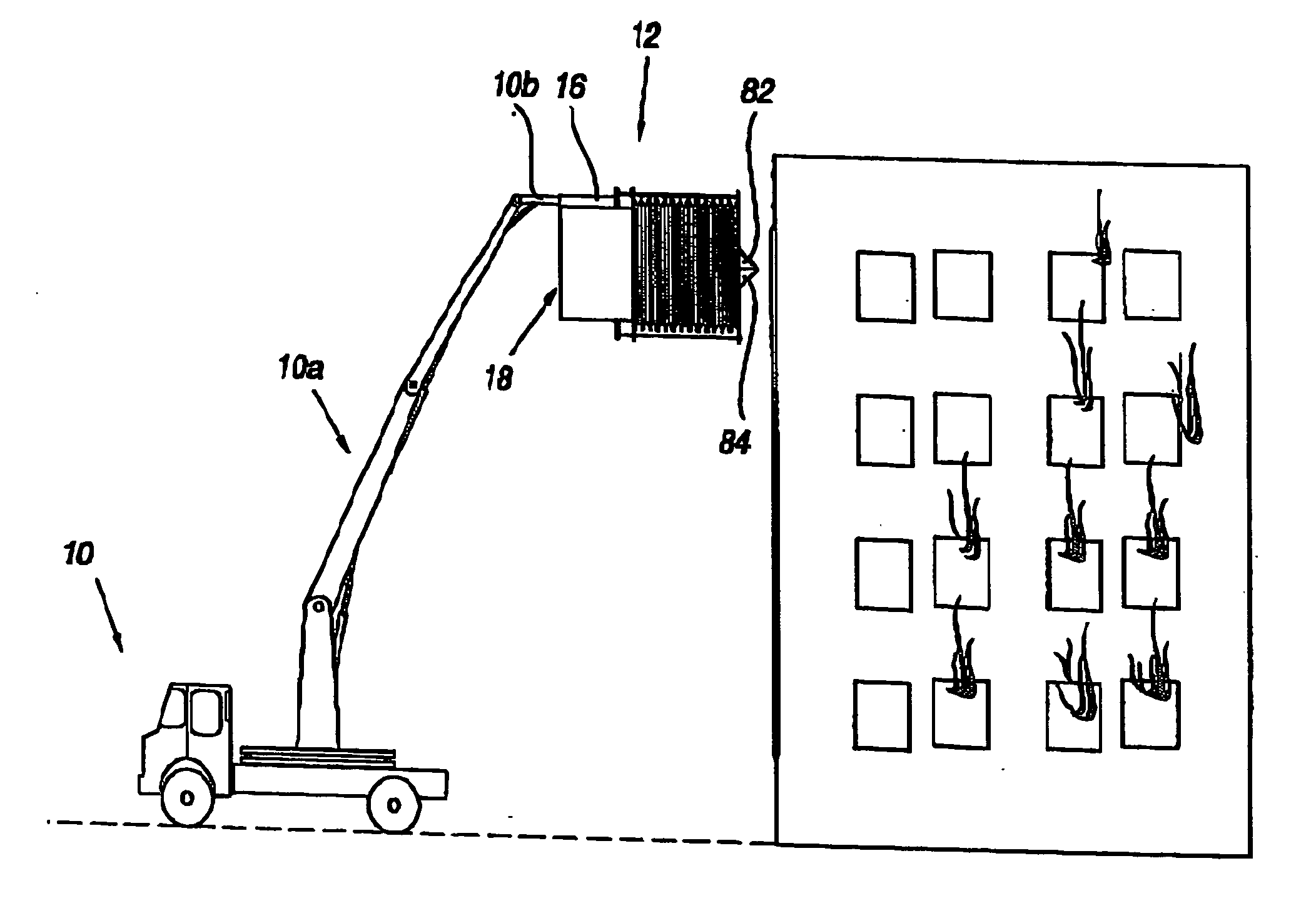
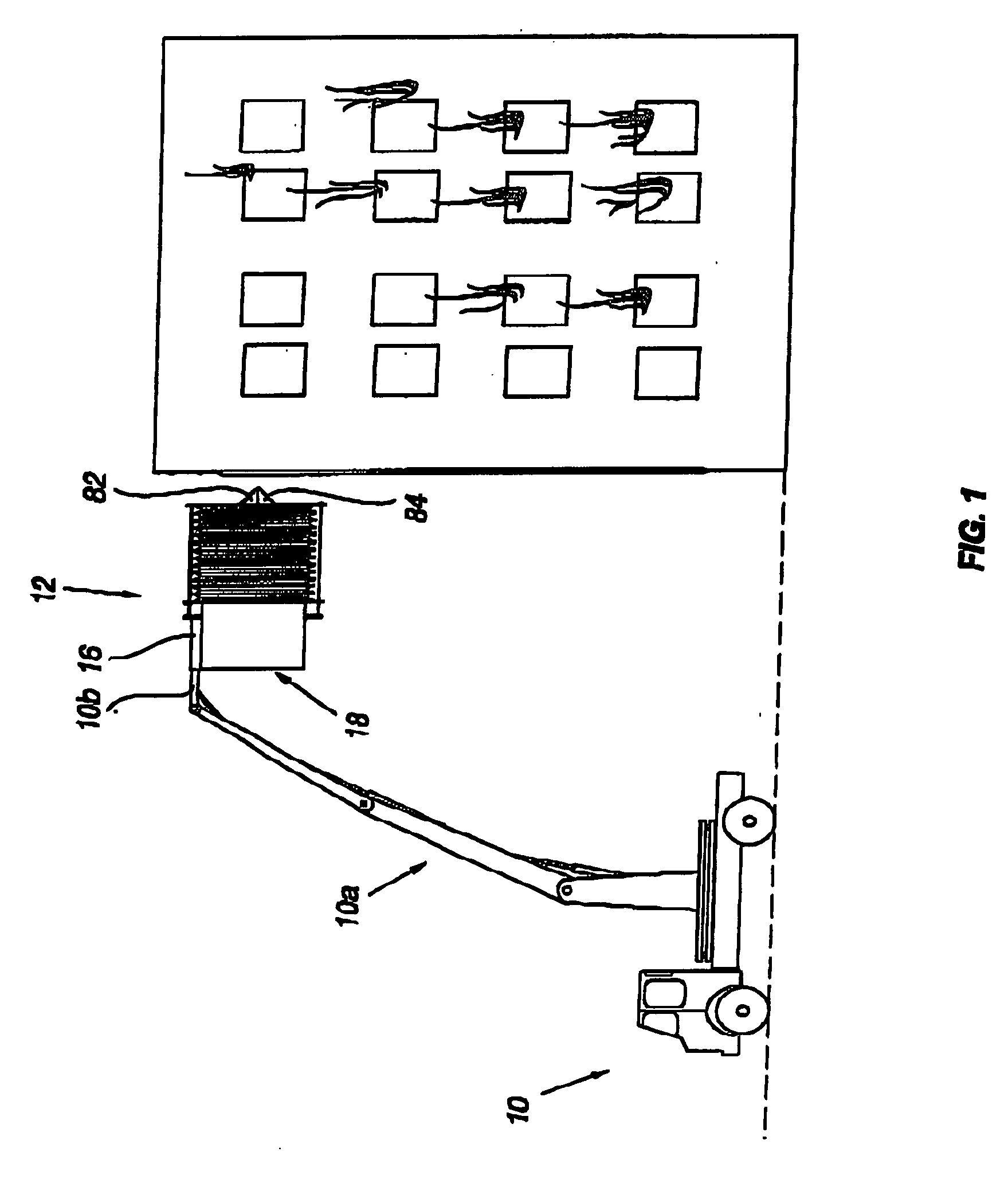
[0018] As shown in FIG. 1, lifesaving crew truck 10 is equipped with a hydraulic boom 10a, carrying and lifting, by beam 10b, a rescue sleeve compartment 12. The beam is freely insertable into and retractable from channel 16 as will be explained below.

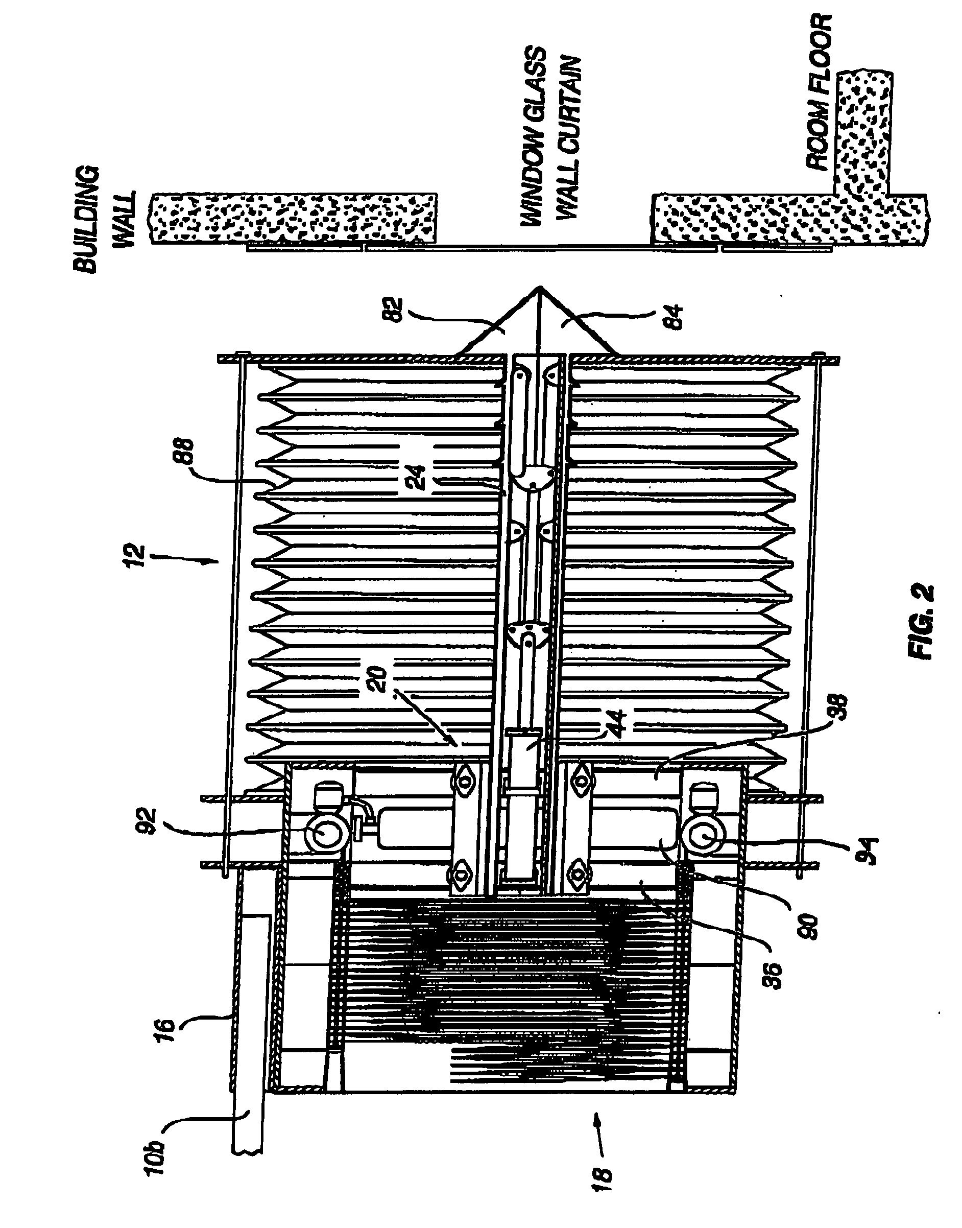
[0019] The compartment 12 accommodates at the exit side thereof a rescue sleeve 18 (FIG. 2), e.g. of the type disclosed in the WO Patent, in the folded, standby state.

[0020] The other, entrance side of the compartment 12 stores a window-breaking ram-and-jaws system generally denoted 20.

[0021] The system 20 comprises two identical, symmetrically located ram-head displacing sub-systems 22a and 22b, operating in parallel as will now be described with reference to FIGS. 5-8. The description will refer in detail to the sub-system 22a, since the other, 22b is identical.

[0022] Referring to FIG. 5 there are provided a pair of L-shaped rails 24 and 26. The ram 24 is affixed to rail 28 and rail 26 to rail 30. The rail 28 is carried by roller...


PUM


Abstract

A rescue system for evacuating individuals through a window frame of a high-rise building. The rescue sleeve (18) is foldable between a compact, standby position and an extended, sloping down to ground level position. Means (92, 94) are provided for activating the ejection of the sleeve (18) from the standby position within a compartment (12) to the extended position. The system (20) is operable to anchor the compartment (12) to the window frame in a self-supporting fashion.

Description

FIELD OF THE INVENTION [0001] The present invention relates to rescue systems for evacuating individuals trapped in high rise buildings in case of emergency situations such as fire or earthquake of the type disclosed in my PCT / IL00 / 00477 Patent Application published as WO 01 / 62138 on Aug. 30, 2001 (hereinafter called “the WO Patent”), the contents of which being hereby incorporated by reference. BACKGROUND OF THE INVENTION [0002] The systems disclosed in the WO Patent and further developments thereof (cf. my Israel Patent Application Nos. 139549, 139550, 145935, 147975) are stationary, namely designed to be permanently installed in buildings from which survivors are to be evacuated. [0003] Therefore, salvation from “ordinary” high-rise buildings solely depends on the conventional firemen vehicular ladders. These ladders are of limited capacity in terms of height and evacuation rate. [0004] Hence, it is the general object of the present invention to provide a mobile rescue sleeve sys...

Claims


Application Information

Patent Timeline
IPC IPC(8): E04G3/00A62BA62B1/20B66F11/04
CPCA62B1/20B66F11/044
Inventor NIR, ELIYAHU
Owner CAMPINA BV
Why Eureka
Try Eureka