Water jet aerator with three-part body and with optional shaped nozzle

a water jet aerator and body technology, applied in the direction of burners, physical therapy, combustion types, etc., can solve the problems of inconvenient attachment of water and air lines, difficulty in changing orientation, and inability to change orientation, so as to improve aeration and improve massage and/or visual effects, the effect of improving the aeration

Inactive Publication Date: 2006-07-13
CUSTOM MOLDED PROD
View PDF7 Cites 10 Cited by
  • Summary
  • Abstract
  • Description
  • Claims
  • Application Information

AI Technical Summary

Benefits of technology

[0012] This invention also is an improved water jet aerator utilizing the three-part body design in conjunction with a nozzle design potentially having improved aeration and / or a more aesthetically pleasing flow pattern. The potentially improved aeration can have a positive affect on the massage and / or therapeutic action of the aerated water jet emanating from the water jet aerator and the more aesthetically pleasing flow pattern can nave a positive affect on the visual aspects of the artifice water structure. The potentially improved aeration and aesthetically pleasing flow pattern are created by a nozzle configuration having a generally “+” or “x” shape.
[0013] The nozzle comprises a base and a spout. The base can be a common eyeball base holding the nozzle in the water jet aerator and allowing the nozzle to be directionally pivoted. The spout, however, has a shape and structure comprising a generally parallelogram-like arrangement with four inwardly curved sides, giving the nozzle a somewhat “+” or “x” shaped appearance when viewed head on. The nozzle preferably is attached to the aeration chamber so that adjustments to the nozzle can produce changes in the flow of the aerated water stream through the water jet aerator such as, for example by swiveling the nozzle so that the direction of flow into the spa can be varied according to the final direction of the nozzle. The nozzle, particularly the spout, may result in an aerated water stream potentially with improved aeration. Further, some people may find that the aerated water stream emanating from the nozzle, that is the pattern of bubbles through the preferred “+” or “x” shaped outlet in the nozzle, is aesthetically appealing.
[0014] The water flow to the aeration chamber preferably may be shut off by rotating the face cover, which thereby rotates the nozzle core assembly such that the core assembly opening rotates away from and therefore closes the water inlet port. The flow volume of water preferably also can be proportionally reduced by only partially rotating the face cover to a position where only a portion of the water core assembly opening is open, thus reducing the cross-sectional area of the water inlet port.
[0015] In operation and use, aerated water flows from the aeration chamber through the nozzle. The aerated water stream is discharged through the shaped nozzles, such as the “+” or “x” shaped nozzle outlet, resulting in the potentially increased aeration and aesthetics. In a typical installation, several water jet aerators are installed around the perimeter of a spa so to form a circuit of aerators.

Problems solved by technology

If this orientation is inconvenient, it is difficult if not impossible to change, and this orientation may prove difficult or inconvenient for attaching the water and air lines.

Method used


Image

  • Water jet aerator with three-part body and with optional shaped nozzle
  • Water jet aerator with three-part body and with optional shaped nozzle
  • Water jet aerator with three-part body and with optional shaped nozzle

Examples


Embodiment Construction

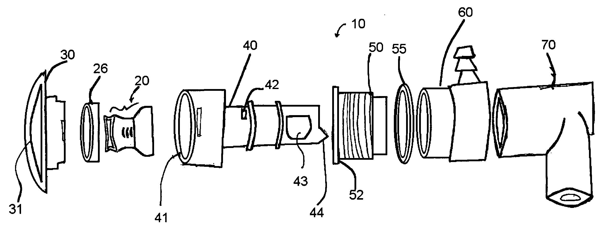
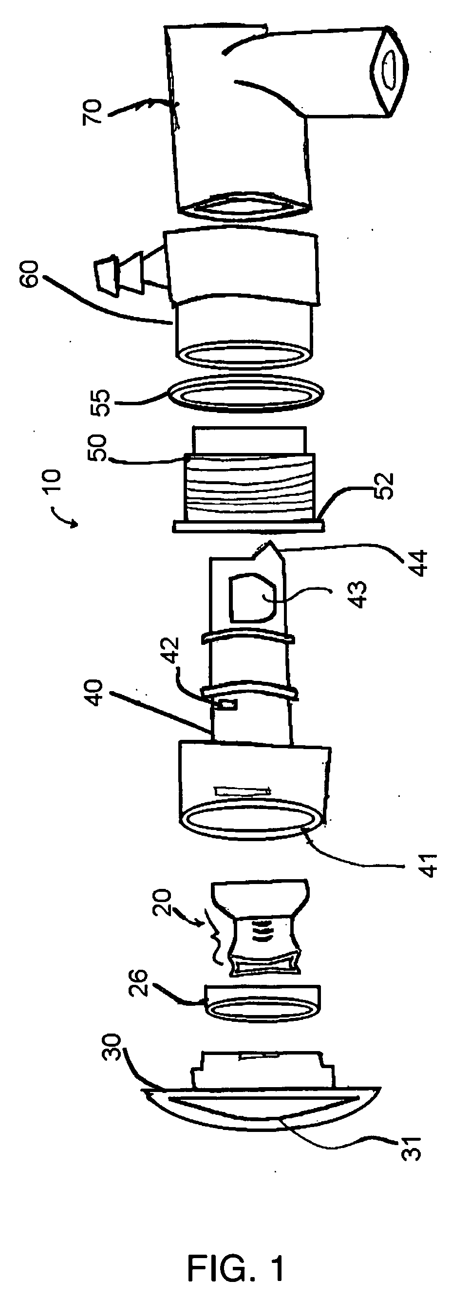
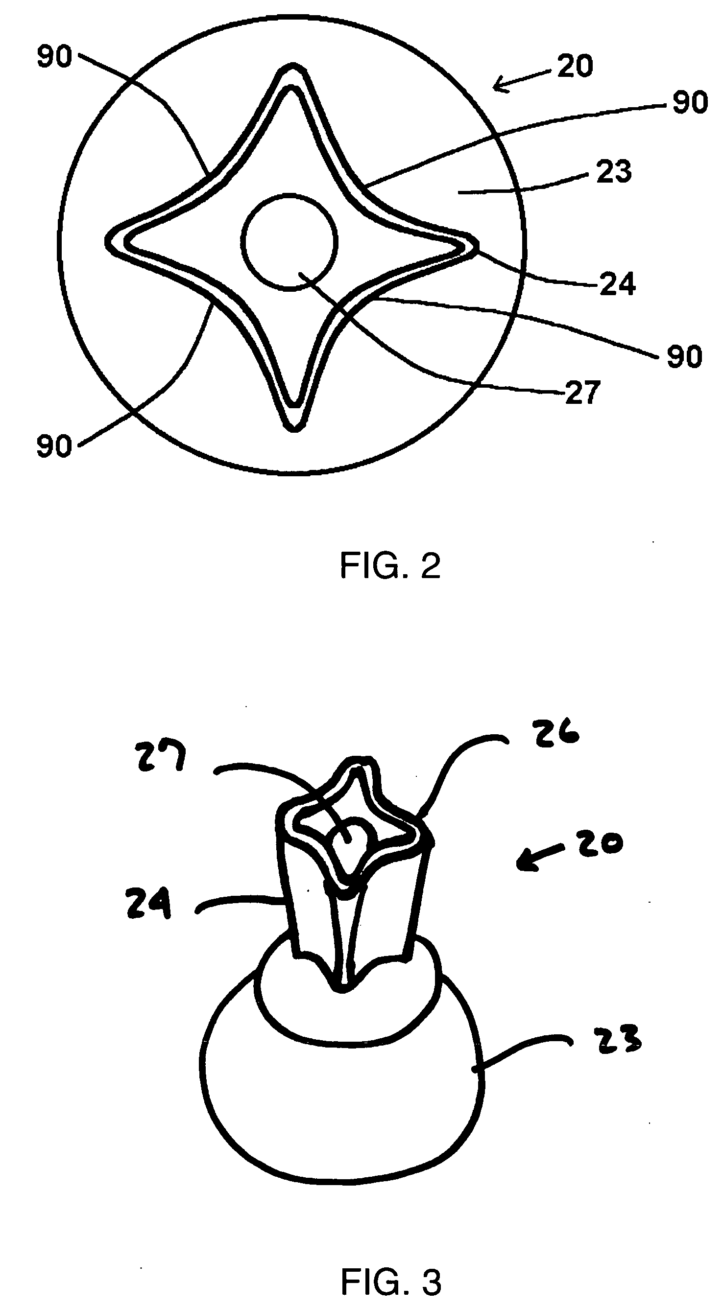
[0022] Illustrative embodiments of the best mode of the present invention include a water jet aerator that may be installed into the walls of an artificial water structures, collectively termed spas herein. Referring to the illustrative figures, FIG. 1 is an exploded perspective side view of one embodiment of the water jet aerator of the present invention showing the various structural components. FIG. 2 is a front view of the nozzle shown in the water jet aerator in FIG. 1 showing the preferred “+” or “x” shaped nozzle outlet. FIG. 3 is a perspective view of the nozzle shown in FIG. 2. FIG. 4 is a side view of an assembled water jet aerator as it would be attached to a spa. FIG. 5 is a sectional side view of the three-part body of the present invention in the assembled water jet aerator as shown in FIG. 4, but showing only the three main parts of the body. While the invention is described herein in conjunction with the preferred and illustrative embodiments, it will be understood t...


PUM


Abstract

A water jet aerator comprising a three part body that can be assembled on site so as to allow the installer to orient the water inlet port and the air inlet port in any orientation and an optional nozzle having a spout with at least four inwardly curved sides.

Description

STATEMENT OF RELATED APPLICATIONS [0001] This patent application is based on and claims priority on U.S. provisional patent application No. 60 / 640,346 having a filing date of 30 Dec. 2004.BACKGROUND OF THE INVENTION [0002] 1. Technical Field [0003] This invention relates generally to equipment for artificial water structures, such as pools, spas and hot tubs. More particularly, this invention relates to the body and nozzle structures of water jet aerators for use in these artificial water structures. [0004] 2. Prior Art [0005] Water jet aerators can be used in artificial water structures, such as pools, spas and hot tubs, to provide jets of aerated water to provide a massaging and therapeutic action. The massaging and therapeutic action usually is provided by water jet aerators that are recessed into the walls of the artificial water structures. Several water jet aerators are usually spaced about the perimeter of an artificial water structure. In some water jet aerators, the nozzles...

Claims


Application Information

Patent Timeline
Patent Type & Authority Applications(United States)
IPC IPC(8): B05B1/28B05B7/04B05B1/00A62C31/00
CPCA61H33/027A61H33/6052A61H33/6063
Inventor LI, H. CHARLES
Owner CUSTOM MOLDED PROD
Why Eureka
Try Eureka