Plasma display apparatus and driving method thereof

a technology of plasma display and driving method, which is applied in the direction of lighting and heating apparatus, lighting device details, instruments, etc., can solve the problems of reducing the lifespan of the plasma display panel, affecting the performance of the display panel, and affecting the display effect of the above-described phosphor, so as to improve the sustain pulse of the sustain period, enhance driving efficiency, and improve the effect of bright afterimag

Inactive Publication Date: 2006-07-13
LG ELECTRONICS INC
View PDF7 Cites 11 Cited by
  • Summary
  • Abstract
  • Description
  • Claims
  • Application Information

AI Technical Summary

Benefits of technology

[0040] It is an object of an embodiment of the present invention to reduce generation of a bright afterimage by improving the sustain pulse of the sustain period.
[0041] It is another object of an embodiment of the present invention to enhance driving efficiency by improving the sustain pulse of the sustain period.
[0045] The present invention can improve the sustain pulse of the sustain period. Therefore, there are advantages in that driving efficiency can be enhanced and a bright afterimage can be improved.

Problems solved by technology

In the related art plasma display panel driven as described above, if a discharge is locally generated on the display surface of the panel, a problem arises because an afterimage, e.g., a bright afterimage is usually generated.
In this case, the above-described phosphor is in a very unstable state when a plasma display panel is first manufactured.
This results in a reduced lifespan of the plasma display panel.
However, problems arise in that a load effect and an erroneous discharge occurrence ratio at high temperature abruptly rise and margin is also reduced.

Method used


Image

  • Plasma display apparatus and driving method thereof
  • Plasma display apparatus and driving method thereof
  • Plasma display apparatus and driving method thereof

Examples


Embodiment Construction

[0063] Embodiments of the present invention will be described in a more detailed manner with reference to the drawings.

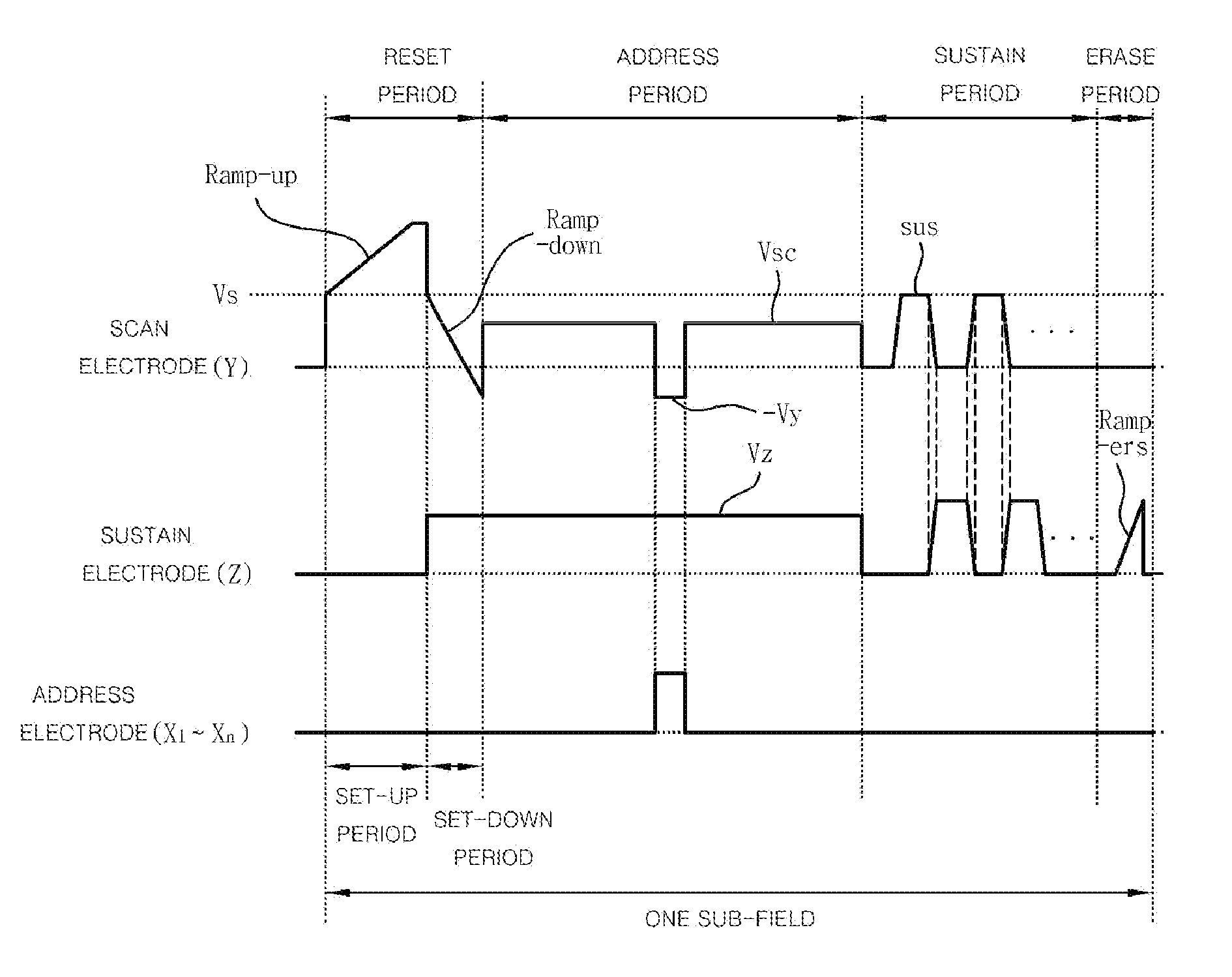
[0064] A plasma display apparatus according to an embodiment of the present invention comprises a plasma display panel comprising a scan electrode and a sustain electrode, a driver for driving the scan electrode and the sustain electrode and a sustain pulse controller for controlling the driver so that a first sustain pulse applied to the scan electrode and a second sustain pulse applied to the sustain electrode are overlapped with each other, and for setting a rising (ER-Up) period of the first sustain pulse applied to the scan electrode and a Y sustain period where the first sustain pulse is maintained at a sustain voltage (Vs) to be different from a rising (ER-Up) period of the second sustain pulse applied to the sustain electrode and a Z sustain period where the second sustain pulse is maintained at the sustain voltage (Vs).

[0065] A point where the first susta...


PUM


Abstract

This document relates to a plasma display apparatus and driving method thereof, and more particularly, to a plasma display apparatus for driving electrodes and driving method thereof. A plasma display apparatus according to an embodiment of the present invention comprises a plasma display panel comprising a scan electrode and a sustain electrode, a driver for driving the scan electrode and the sustain electrode and a sustain pulse controller for controlling the driver so that a first sustain pulse applied to the scan electrode and a second sustain pulse applied to the sustain electrode are overlapped with each other, and for setting a rising (ER-Up) period of the first sustain pulse applied to the scan electrode and a Y sustain period where the first sustain pulse is maintained at a sustain voltage (Vs) to be different from a rising (ER-Up) period of the second sustain pulse applied to the sustain electrode and a Z sustain period where the second sustain pulse is maintained at the sustain voltage (Vs). This document is advantageous in that it can enhance driving efficiency and improve a bright afterimage, by improving a sustain pulse of a sustain period.

Description

[0001] This Nonprovisional application claims priority under 35 U.S.C. §119(a) on Patent Application No. 10-2005-0002353 filed in Korea on Jan. 10, 2005 the entire contents of which are hereby incorporated by reference. BACKGROUND OF THE INVENTION [0002] 1. Field of the Invention [0003] This document relates to a plasma display apparatus and driving method thereof, and more particularly, to a plasma display apparatus that drives electrodes and driving method thereof. [0004] 2. Background of the Related Art [0005] In general, a plasma display apparatus among display apparatuses comprises a plasma display panel and a driver for driving the plasma display panel. [0006] The plasma display panel comprises a front substrate and a rear substrate. A barrier rib formed between the front substrate and the rear substrate forms one unit cell. Each cell is filled with an inert gas containing a primary discharge gas, such as neon (Ne), helium (He) or a mixed gas of Ne+He, and a small amount of xe...

Claims


Application Information

Patent Timeline
Patent Type & Authority Applications(United States)
IPC IPC(8): G09G3/28G09G3/288G09G3/20G09G3/291G09G3/294G09G3/298
CPCG09G3/2942G09G2310/066G09G2320/0257G09G2330/06F21V1/14F21V17/00
Inventor RHEE, BYUNG JOON
Owner LG ELECTRONICS INC
Why Eureka
Try Eureka