Switch with shaped face

a technology of electrical wiring and shaped faces, applied in the direction of contact mechanisms, substation/switching arrangement details, basic electric elements, etc., can solve the problems of time-consuming wall plate installation, misalignment and positioning problems, user visual inconsistency,

Inactive Publication Date: 2006-07-13
LEVITON MFG
View PDF31 Cites 26 Cited by
  • Summary
  • Abstract
  • Description
  • Claims
  • Application Information

AI Technical Summary

Benefits of technology

[0009] The paddle of the switch has a length-width ratio dimension that is proportioned to provide a finger contact surface of increased area to allow a user to more easily and quickly identify and operate a particular switch. The vertical axis of the switch has a surface of positive first differential, comprised of splines drawn between points of varying distance from a datum plane, and has along the horizontal axis a surface of a positive first differential and negative second differential, comprised of a combination of splines drawn between points of varying distance from the datum plane.
[0013] In one embodiment of the switch according to the present invention, an articulated cam driver coupled to the rocker paddle of the switch causes a cam to rotate first in a clockwise direction and then in a counter clockwise direction each time the rocker paddle is depressed. Alternate rotation of the cam drives a slider member back and forth along a linear axis to open and close a set of contacts. A leaf spring of predetermined shape cooperates with a cam follower on the slider member to assist in the movement of the slider and to determine its rest positions. A spring, acting through the rigid member, urges the rocker paddle to always be in its out position when the switch is in its on position and its off at-rest position. An indicator such as an LED located in the paddle indicates the state of conduction of the switch.

Problems solved by technology

In installations where there are multiple wiring devices in a common box, the installation of the wall plate can be time consuming.
Misalignment and positioning problems are often caused by wall boxes that are skewed relative to the wall or by walls which may not be flat.
The irregular in-out positioning of adjacent switches, particularly with 3-way and 4-way switches, can cause visual inconsistency in the mind of the user as to which switch is on and which switch is off when subsequent activation or deactivation of less than all of the rocker switches is desired by a user.
A receptacle with a flat face, when ganged with a switch which is not flat in one plane, typically presents a visual discontinuous array of wiring devices which homeowners seem to find visually objectionable.

Method used


Image

  • Switch with shaped face
  • Switch with shaped face
  • Switch with shaped face

Examples


Embodiment Construction

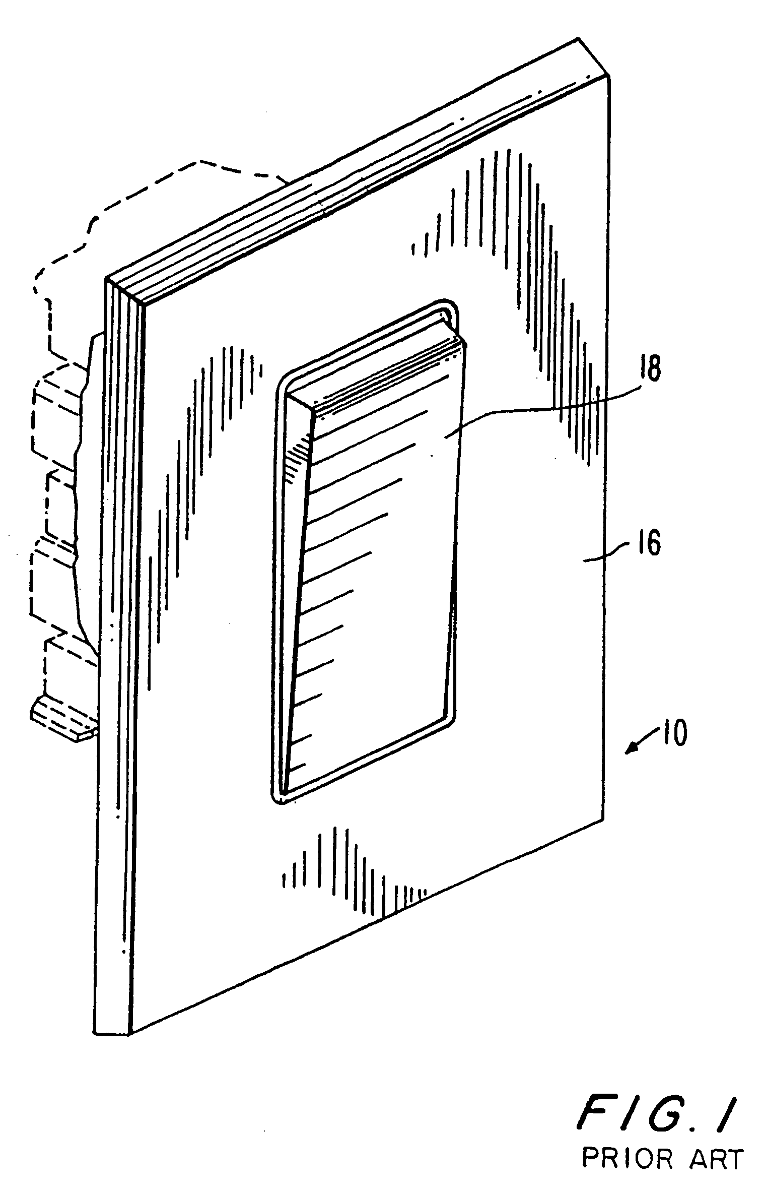
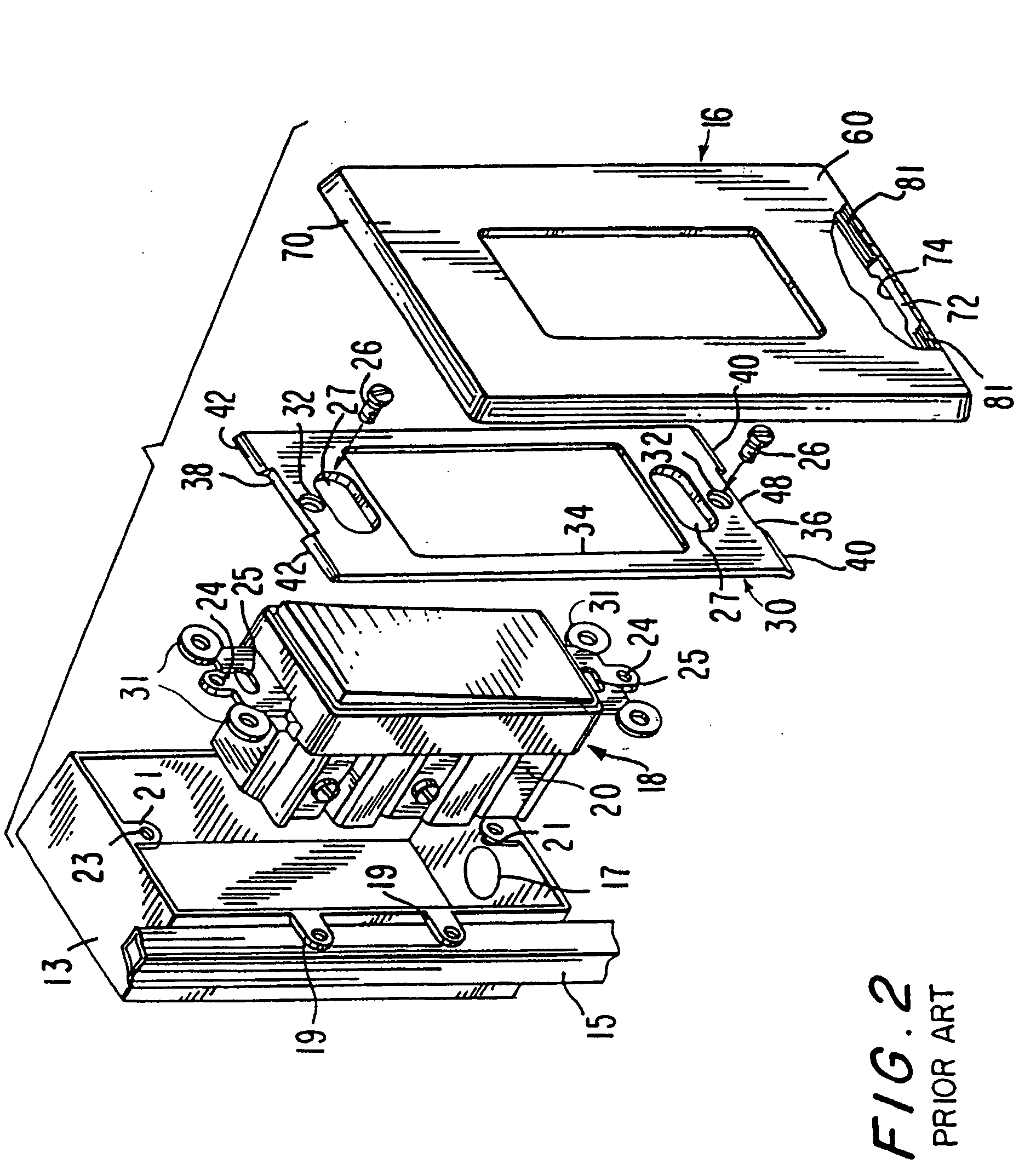
[0062] Referring to FIG. 1, there is illustrated a front perspective view of a prior art “Decora” type electrical wall-type switch 18 and wall plate 16 forming assembly 10. Referring to FIG. 2, there is shown a perspective exploded view of a box 13 and the prior art switch 18, wall plate 16 and attachment plate 30. A suitable aperture is cut into a wall (where there is an existing wall and this installation is not a new construction) to provide access to the box 13 mounted to a stud 15, or to permit installation of a suitable box directly to the material of the wall (such as plasterboard). The box 13 is chosen to be large enough to accept as many wiring devices as are to be mounted therein. The box 13 is made of metal or plastic, depending upon local electrical Code requirements, and has one or more openings in its sides or back to permit the introduction of electrical wiring or cables into the interior of the box 13. Box 13 has mounting means 19 to permit the box to be anchored to ...


PUM


Abstract

There is disclosed structure which overcomes the deficiencies with respect to prior art devices by providing a wiring device such as a switch having a paddle that pivots about its upper end and is biased to assume the same at rest position when either in its on position or off position. Repeated pressing and releasing the lower portion of the face of the switch paddle alternately closes and opens a set of contacts within the switch to alternately connect and disconnect a load form a source of electricity each time the paddle is pressed. Thus, regardless of whether adjacent switches are on-off switches or 3-way switches, they will always be in alignment. An on-off indicator such as a small light is provided to indicate to a user when the contacts of the switch are opened or closed. The paddle of the switch has a length-width ratio dimension that is proportioned to provide a finger contact surface of increased area to allow a user to more easily and quickly identify and operate a particular switch. The vertical axis of the switch has a surface of positive first differential, comprised of splines drawn between points of varying distance from a datum plane, and has along the horizontal axis a surface of a positive first differential and negative second differential, comprised of a combination of splines drawn between points of varying distance from the datum plane.

Description

[0001] This application is a continuation of application Ser. No. 10 / 852,815, filed May 25, 2004, which is a continuation in part of application Ser. No. 10 / 516,765, filed Dec. 3, 2004, which is a continuation in part of application Ser. No. 10 / 388,555, filed Mar. 14, 2003, which is a continuation of application Ser. No. 10 / 236,642, filed Sep. 6, 2002, which is a continuation in part of application Ser. No. 10 / 163,546 filed Jun. 6, 2002.BACKGROUND OF THE INVENTION [0002] 1. Field of the Invention [0003] The present invention relates generally to the field of electrical wiring devices such as, by way of example, electrical switches and / or receptacles and accessories for said switches and / or receptacles of the type installed in building walls. [0004] 2. Description of the Related Art [0005] When modifying the wiring in an existing building, whether public, commercial or residential by adding a wiring device such as a switch, a receptacle or a combination of switches and receptacles, i...

Claims


Application Information

Patent Timeline
Patent Type & Authority Applications(United States)
IPC IPC(8): H02B1/00H02G3/14
CPCH01H23/025H01H23/143H02G3/14
Inventor KUREK, STEPHEN R.ENDRES, PAULTUFANO, ANTHONYODDSEN, DENNIS A.
Owner LEVITON MFG
Why Eureka
Try Eureka