
Adapter device for mounting a ceiling electrical light fixture

a technology for adapters and ceiling electrical light fixtures, which is applied in fixed installation, lighting support devices, lighting and heating apparatus, etc. it can solve the problems of affecting the arrangement, affecting the installation effect, so as to simplify the installation of cumbersome electrical lighting fixtures and save installation costs. , the effect of saving tim

Inactive Publication Date: 2006-07-13
FIFTH THIRD BANK AS COLLATERAL AGENT
View PDF10 Cites 4 Cited by
  • Summary
  • Abstract
  • Description
  • Claims
  • Application Information

AI Technical Summary

Benefits of technology

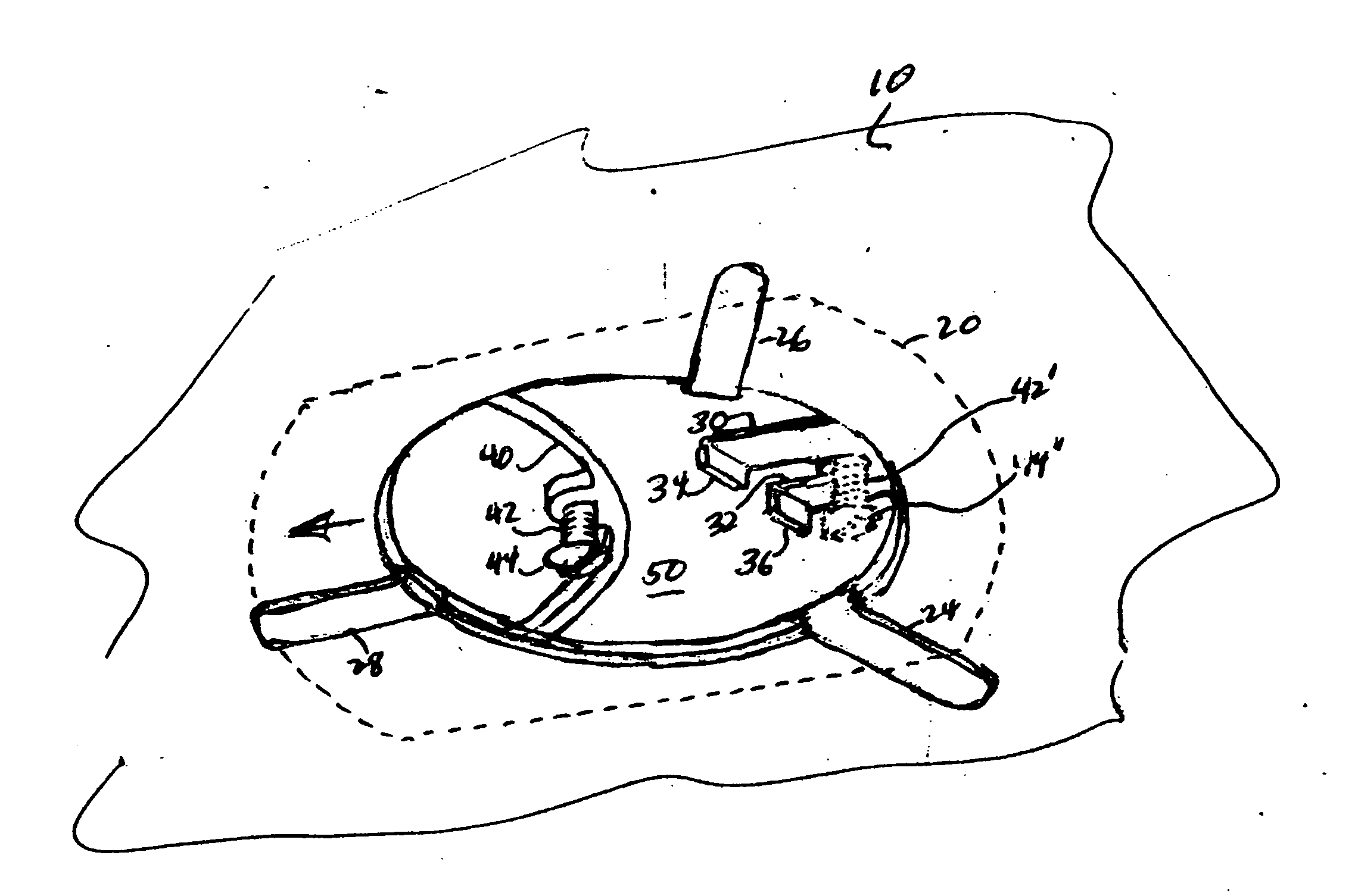
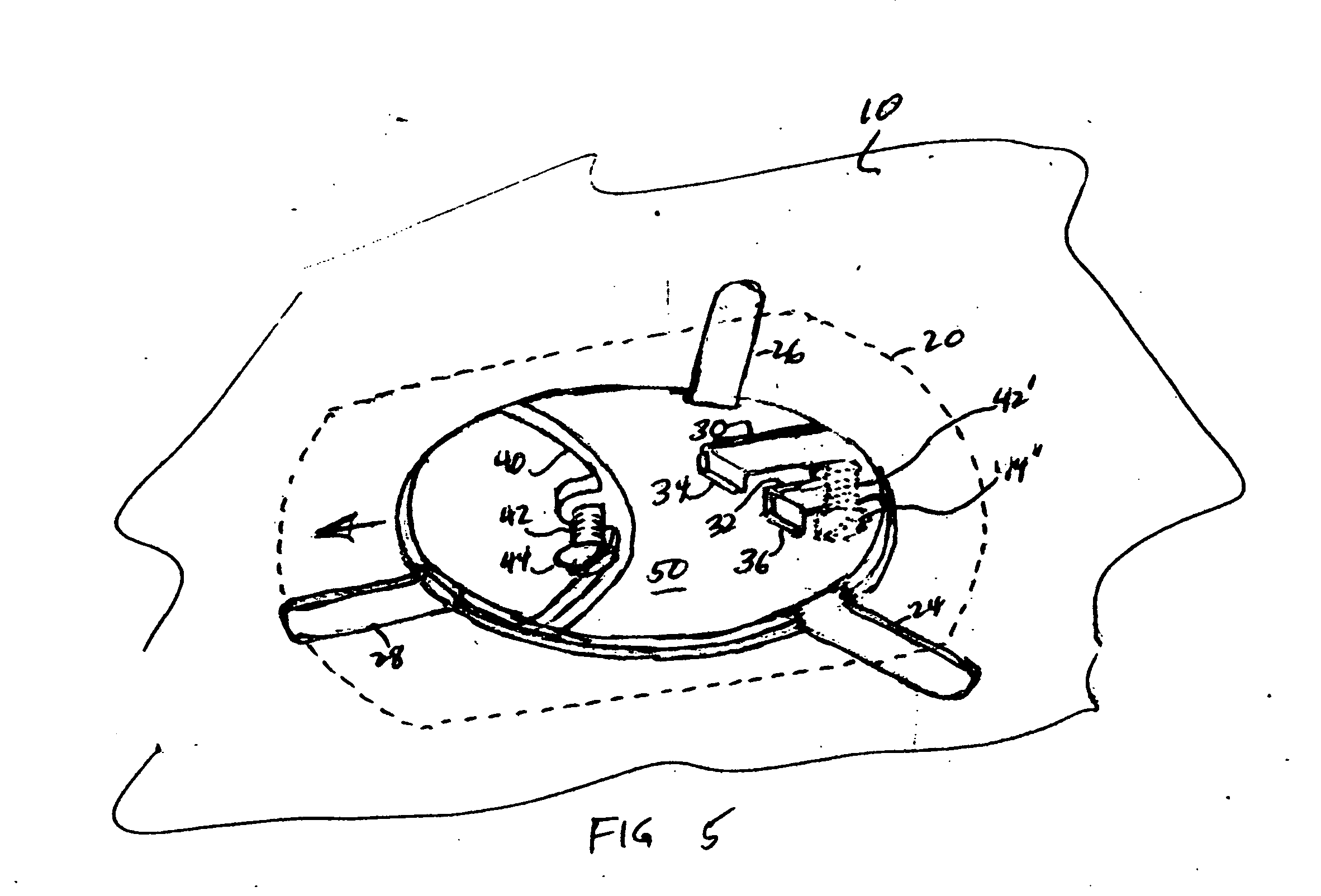
[0005] The present invention comprises a very simple, economical method and apparatus for simplified installation of cumbersome electrical lighting fixtures. It includes an adapter that is secured to the light fixture, without fasteners, which enables the light fixture to be temporarily suspended from the cover screw of an electrical box in the ceiling to enable electrical and mechanical installation of the light fixture by one person. While a fluorescent light fixture is described, it will be appreciated that the invention is directed to any cumbersome electrical light fixture. OBJECTS OF THE INVENTION
[0007] Another object of the invention is to provide an economical method and apparatus for enabling one person installation of a ceiling mounted electrical light fixture.
[0008] A further object of the invention is to provide an adapter for a standard fluorescent fixture to simplify its installation.
[0009] A feature of the invention is the provision of a simple, readily installed adapter for enabling ceiling installation of a cumbersome light fixture by one person.

Problems solved by technology

The adapter plate requires separate installation and the lighting fixture must have non-standard mounting studs, both of which detract from the benefits of the arrangement.
The arrangement involves the installation of a separate mounting base and a mating removable bracket, which is relatively costly and time consuming.

Method used


Image

  • Adapter device for mounting a ceiling electrical light fixture
  • Adapter device for mounting a ceiling electrical light fixture
  • Adapter device for mounting a ceiling electrical light fixture

Examples


Embodiment Construction

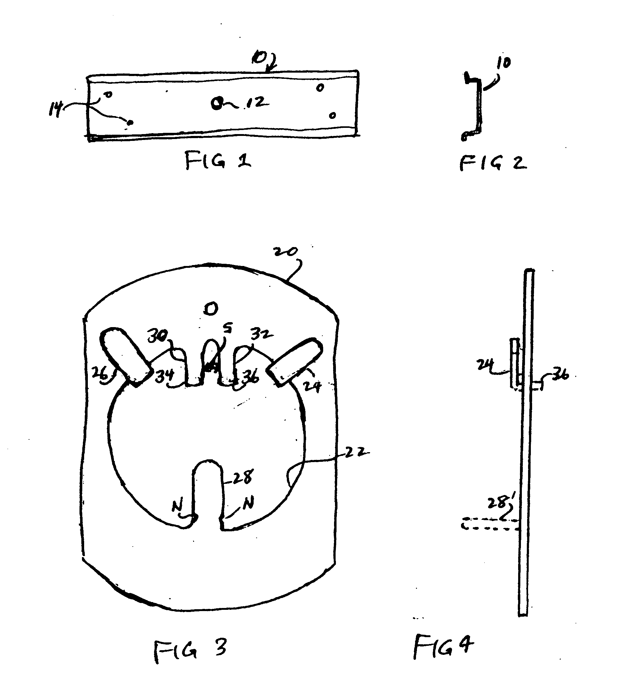
[0019]FIGS. 1 and 2 are not-to-scale views of a body 10 of a conventional fluorescent light fixture. The body 10 includes a centrally located electrical access hole 12 for permitting electrical connections to be made between the elements of the fluorescent fixture and the installation's electrical wiring (neither of which is shown). A plurality of mounting holes 14 are provided in body 10 for securing the fluorescent light fixture to a ceiling. It will be appreciated that elements of the fluorescent light fixture, such as sockets, wiring, ballasts and bulbs are not shown. These elements are well known and form no part of the present invention. All of the elements, with the exception of the bulbs, are generally secured to the body 10 at the time of installation of the fluorescent fixture. It will therefore be appreciated that the weight of the light fixture is considerable as well as cumbersome since it is up to eight feet long and fifteen or more inches wide. Consequently installati...


PUM


Abstract

An adapter device, for enabling installation of an electrical light fixture to a ceiling mounted electrical box by one person, includes an opening into which a plurality of bendable tabs and a cover screw engaging yoke extend. The adapter device is affixed in an electrical access hole in the body of the electrical light fixture and enables the light fixture to be temporarily suspended from the partially unscrewed cover screw on the electrical box. The temporarily suspended light fixture may be readily aligned with adjacent walls, etc., rotated to enable installation of permanent support anchors, and repositioned to permanently secure it to the installed support anchors.

Description

BACKGROUND OF THE INVENTION [0001] This invention relates generally to the overhead installation of a cumbersome electrical light fixture, such as a fluorescent light fixture, and in particular to a method and apparatus for enabling one person to install a cumbersome electrical light fixture to a ceiling-mounted electrical box. [0002] Installation of a relatively large electrical light fixture, to a ceiling generally requires two persons or the provision of separately installed adapter devices on the ceiling. The prior art includes a number of patents describing devices for aiding in the installation of such cumbersome light fixtures. Among these patents are the following. [0003] U.S. Pat. No. 2,433,819, issued Dec. 30, 1947 to K. Scribner in which a separate plate, having a plurality of downwardly projecting slotted tabs for embracing studs in the sides of a lighting fixture, is secured to the ceiling. The adapter plate requires separate installation and the lighting fixture must h...

Claims


Application Information

Patent Timeline
Patent Type & Authority Applications(United States)
IPC IPC(8): F21S8/00
CPCF21V21/02F21V21/025
Inventor BLACKMAN, STEPHENSTABELFELDT, GARY
Owner FIFTH THIRD BANK AS COLLATERAL AGENT
Learn More