
Image forming apparatus and method of image forming

Inactive Publication Date: 2006-07-13
KONICA MINOLTA BUSINESS TECH INC
View PDF3 Cites 24 Cited by
  • Summary
  • Abstract
  • Description
  • Claims
  • Application Information

AI Technical Summary

Benefits of technology

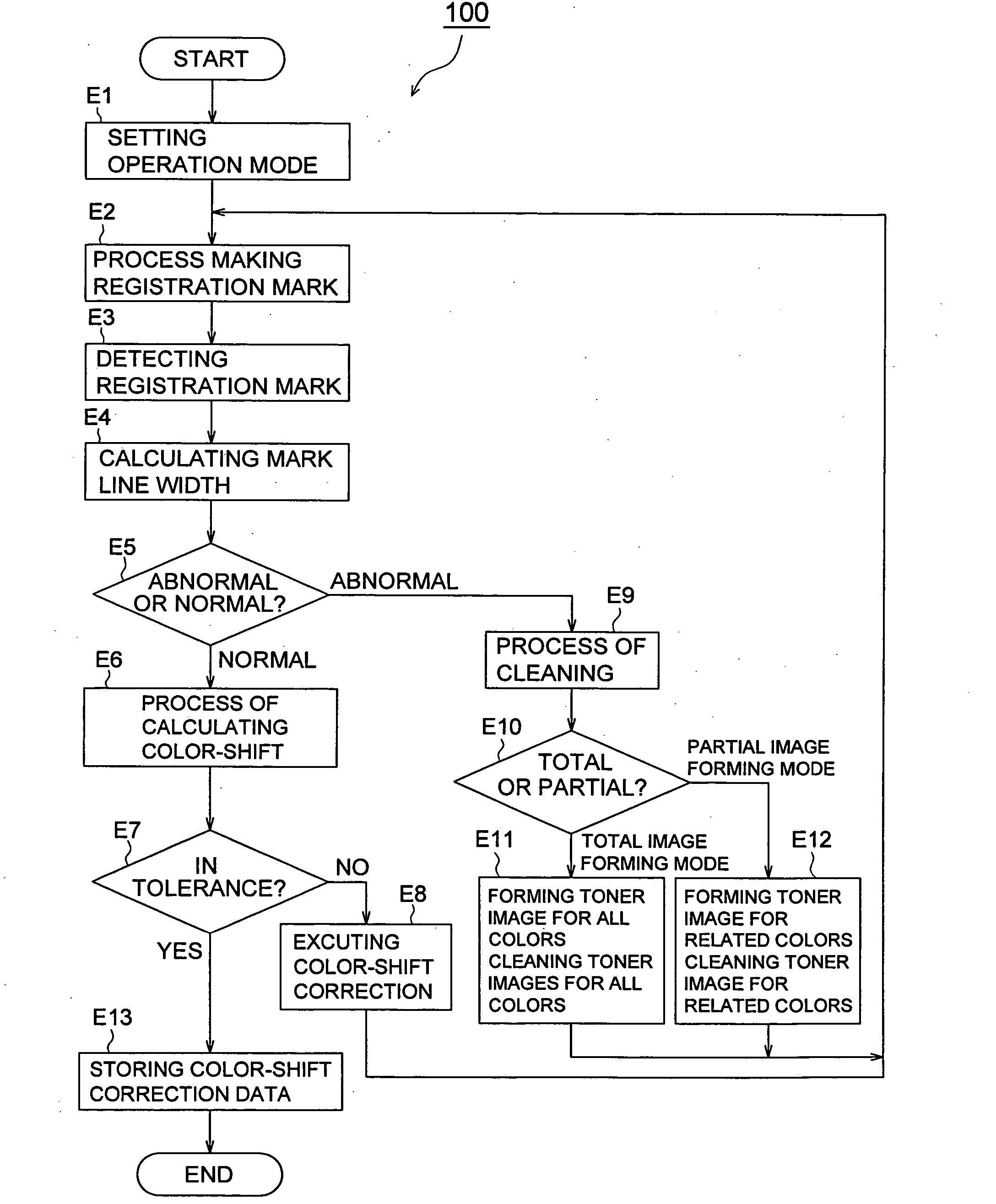
[0029] wherein during the execution of the color-shift-correcting mode, where the image forming section forms the registration mark on the image carrier, the control section detects the amount of the position shift of the registration mark and the control section corrects a position of an image according to the amount of the positional shift, the control section calculates the line width of the registration mark from the image detection signal and then compares the line width of the registration mark with a reference value of line width to d

Problems solved by technology

i. When a white spot phenomenon is generated for some reasons on a registration mark, when practicing a color-shift-correcting mode in a color image forming apparatus shown in Patent Document 1 or in a color image recording apparatus shown in Patent Document 2, there is a risk that an amount of color-shift cannot be calculated precisely.
If this white spot portion of the registration mark is detected by the registration mark sensor, the mark is detected to be thinner than a width of the reference line in the design of the mark, resulting in a problem that an error is caused in a calculated value of a distance between marks, and in a risk that a precise amount of color-shift cannot be calculated.
Thus, the number of data is reduced by an amount corresponding to the excluded data, resulting in lowered reliability such as an average value.
Therefore, even when the color balance adjusting technology of this kind is applied on the color-shift correcting mode as it is, it is impossible to calculate a distance between respective colors for Y, M, C and BK.
Further, on the color-shift-correcting mode, there is even a risk that toner of each color for respective colors of Y, M, C and BK are used wastefully, because toner for respective colors for Y, M, C and BK are not superposed.

Method used


Image

  • Image forming apparatus and method of image forming
  • Image forming apparatus and method of image forming
  • Image forming apparatus and method of image forming

Examples


Embodiment Construction

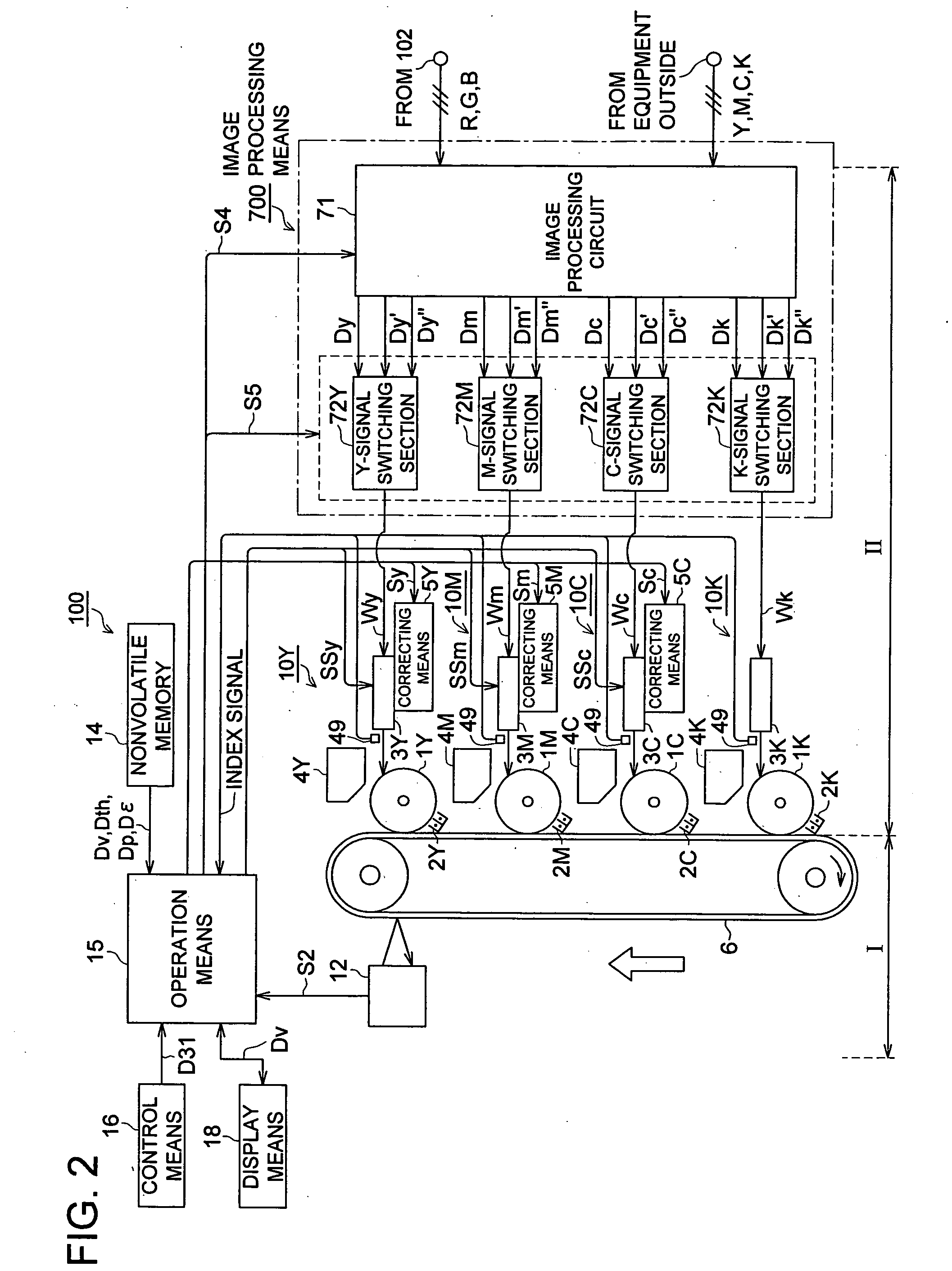
[0042] An aspect of the invention is an image forming apparatus that forms color images on an image carrier wherein, when a color-shift-correcting mode represents an operation to form a print image for correcting color-shift on an image carrier, an operation to read timing of passing of the print image, an operation to calculate an amount of positional shift of the print image for another color for a print image of the reference color and an operation to correct the image forming position based on an amount of the positional shift, while an image forming system restoration mode represents an operation to form an image for adjusting an image forming system on an image carrier and an operation to remove an image for adjusting an image forming system formed on the image carrier, there are provided an image forming section that forms a print image for correcting color-shift on the image carrier, an image detecting section that outputs an image detection signal representing a line width ...


PUM


Abstract

When conducting a color-shift-correcting mode using a registration mark formed by the image forming means on an image carrier, the image detecting means outputs the image detection signal representing the line width of the registration mark and the control section calculates the line width of the registration from the image detection signal. The control means compares a line width of the registration mark with a predetermined reference value of the line width to discriminate between abnormality and normality. If normality, the control means continues the color-shift-correcting mode and if abnormality the control means conducts the image forming system restoration mode after stopping the execution of the color-shift-correcting mode. Therefore, even in the case where a white spot is generated for some reasons on the registration mark, the color-shift-correcting mode can be conducted on the normal registration mark with the help of the image forming system restoration mode.

Description

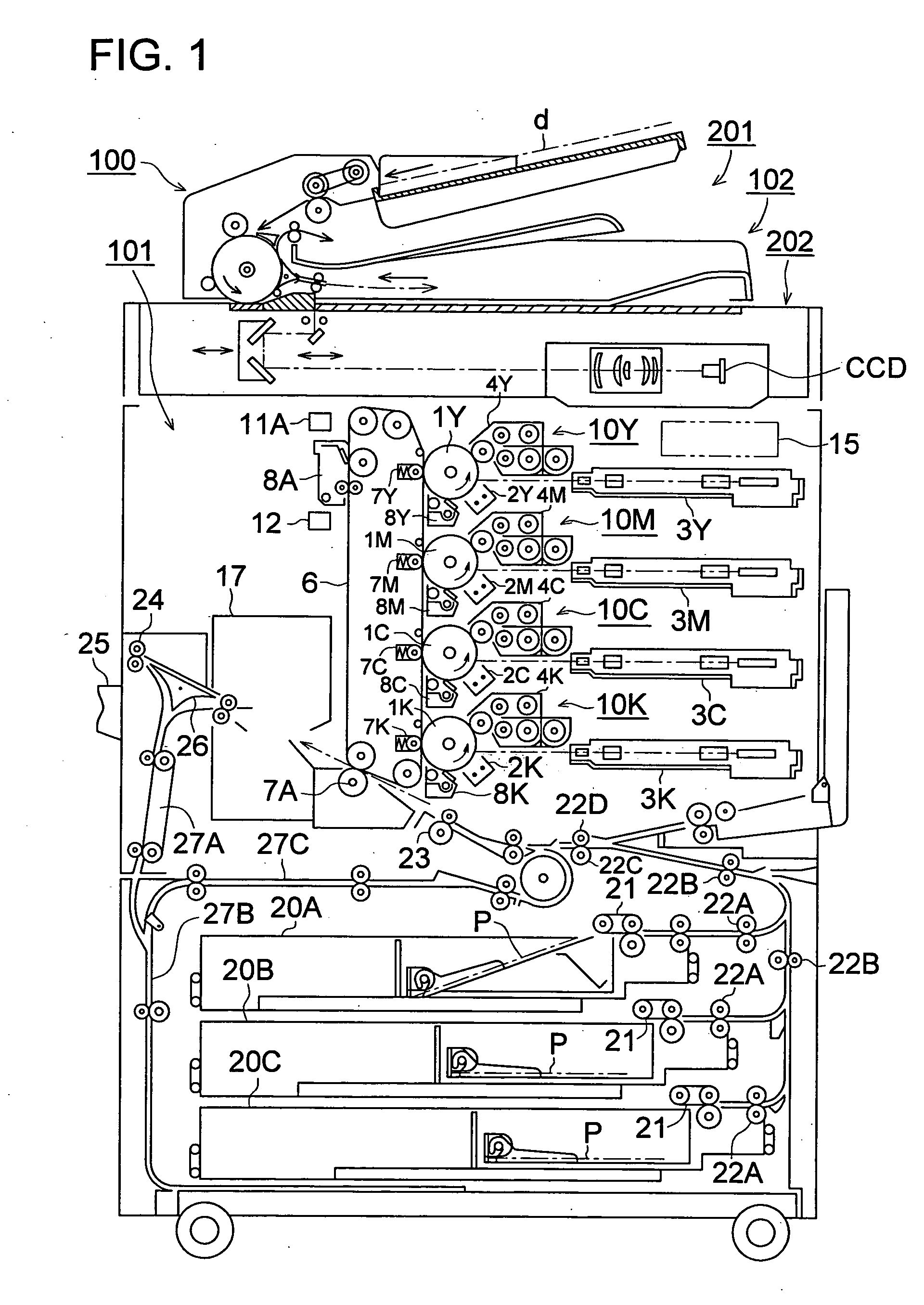
BACKGROUND [0001] 1. Field of the Invention [0002] The present invention relates to an image forming apparatus which is suitably applied to a color printer and a color copying machine both of a tandem type each having a photoconductor drum and further a color-shift-correcting mode and a color multifunctional machine composed of the aforesaid printer or the copying machine, and to an image forming method. [0003] 2. Description of Related Art [0004] A color printer and a color copying machine both of a tandem type and a color multifunctional machine composed of the aforesaid printer or the copying machine have become popular in recent years. In each of these color image forming apparatus, there are provided a laser writing unit, a developing unit, a photoconductor drum, an intermediate transfer belt and a fixing unit, for each of yellow (Y), magenta (M), cyan (C) and black (BK) colors. [0005] For example, the laser writing unit for Y color is arranged so that it draws an electrostatic...

Claims


Application Information

Patent Timeline
IPC IPC(8): G03G15/01
CPCG03G2215/0119G03G15/0194G03G2215/0158
Inventor NISHIKAWA, EIJIOKUTOMI, RYUJIOGATA, SATOSHIUEDA, TADAYUKI
Owner KONICA MINOLTA BUSINESS TECH INC
Learn More