

Methods and apparatus for detection of large leaks in sealed articles
a technology for sealing articles and leaks, applied in the direction of measuring devices, instruments, structural/machine measurement, etc., can solve the problems of difficult or impossible to reach the required pressure level, the inlet of the mass spectrometer tube must be maintained at a relatively low level, and the vacuum pumping cycle is relatively long
- Summary
- Abstract
- Description
- Claims
- Application Information
AI Technical Summary
Benefits of technology
Problems solved by technology
Method used
Image

Examples
first embodiment
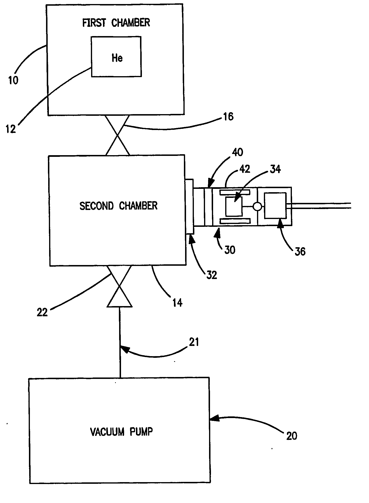
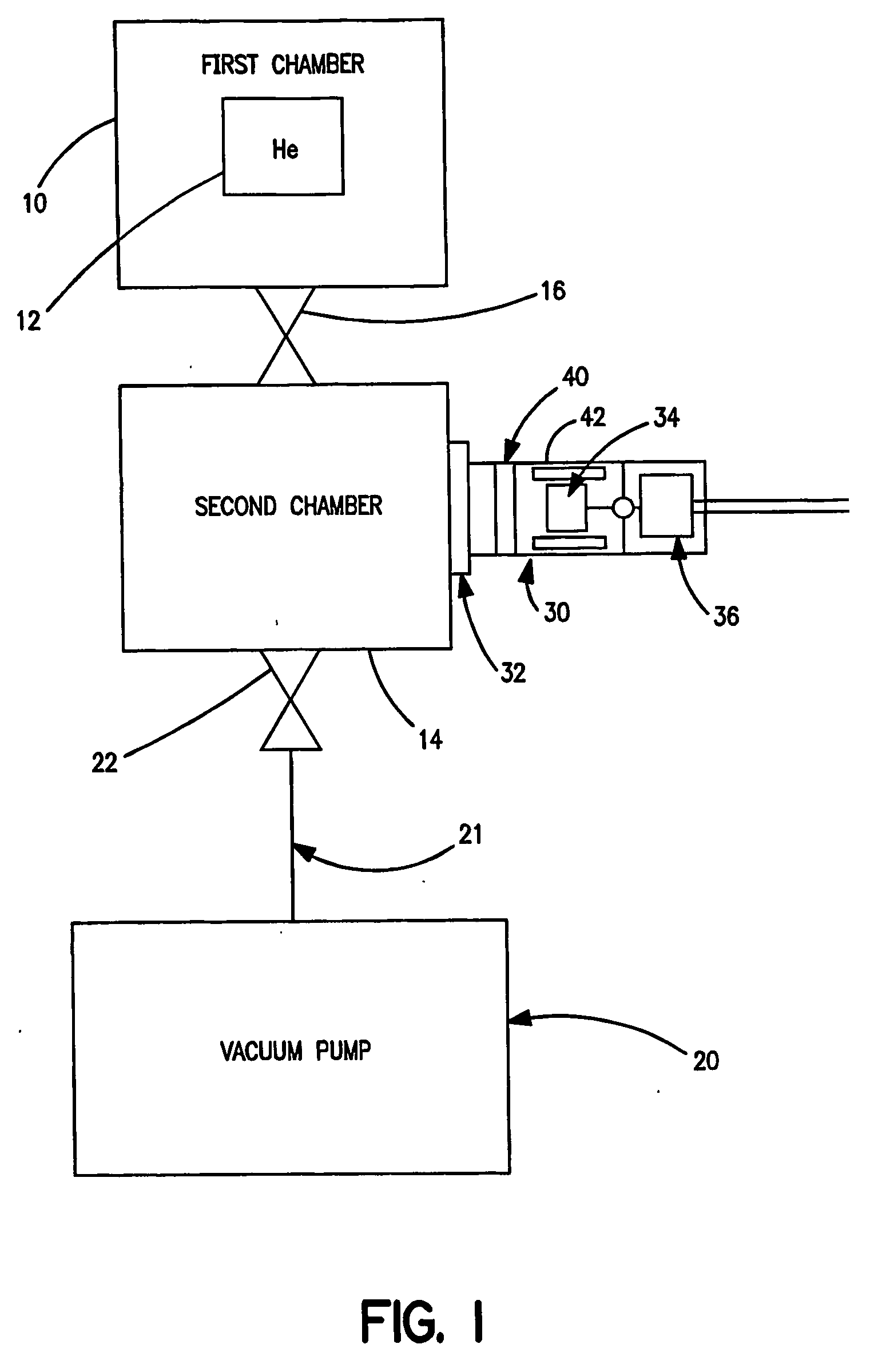
[0020] A schematic block diagram of leak detection apparatus in accordance with the invention is shown in FIG. 1. A first sealable chamber 10 holds a test piece 12. The internal volume of test piece 12 is pressurized with helium or is exposed to a high helium concentration before being inserted into the first chamber 10 of the leak detection apparatus. A second sealable chamber 14 is connected to first chamber 10 through a first valve 16. A vacuum pump 20 having an inlet 21 is connected through a second valve 22 to second chamber 14. Vacuum pump 20 may be any type able to evacuate down to a pressure of about 100 millibar.
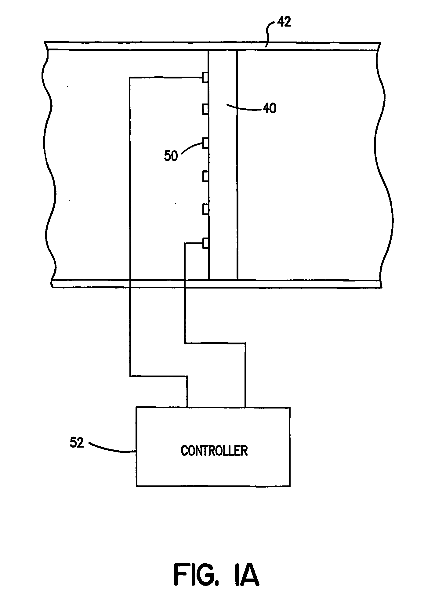
[0021] A helium detector assembly 30 is connected via a vacuum flange 32 to second chamber 14. Helium detector assembly 30 includes an ion pump 34, an ion pump controller 36 and a trace gas permeable member 40. Ion pump 34 and permeable member 40 are mounted in a sealed housing 42 with permeable member 40 interposed between second chamber 14 and ion pump 34. Control...
second embodiment
[0027] A schematic block diagram of leak detection apparatus in accordance with the invention is shown in FIG. 2. Like elements in FIGS. 1 and 2 have the same reference numerals. In the embodiment of FIG. 2, a test port of a leak detector 24 is connected through second valve 22 to second chamber 14. In the embodiment of FIG. 2, vacuum pump 20 is omitted and leak detector 24 includes a suitable vacuum pump that is connectable through valve 22 to second chamber 14. In this embodiment, a fine leak test may optionally be performed after the large leak test. Leak detector 24 may be any leak detector which includes a vacuum pump. An example of a suitable leak detector is shown in FIG. 5 and is described below. However, the leak detector is not limited to the example shown in FIG. 5.
[0028] Chambers 10 and 14 are interconnected by first valve 16, and vacuum pump 20 is connected to second chamber 14 through second valve 22. The helium detector assembly 30 is connected to second chamber 14. W...
third embodiment
[0032] A schematic block diagram of leak detection apparatus in accordance with the invention is shown in FIG. 3. Like elements in FIGS. 2 and 3 have the same reference numerals. In the embodiment of FIG. 3, ion pump 34 and ion pump controller 36 are omitted, and housing 42 is connected by a conduit 50 to the test port of leak detector 24.
[0033] To perform a large leak test, test piece 12 is placed in first chamber 10, and first valve 16 is closed. Second valve 22 is opened, and second chamber 14 is vacuum pumped with the vacuum pump that is part of leak detector 24. Then second valve 22 is closed and first valve 16 is opened. This allows the pressure to equalize between first chamber 10 and second chamber 14. Helium that leaks from test piece 12 passes through permeable member 40, housing 42 and conduit 60 to leak detector 24. The helium is detected by leak detector 24, and the presence or absence of a leak is determined. Because second valve 22 is closed during large leak detectio...
PUM
 Abstract
Description
Claims
Application Information