Slide-out electronic card connector

a technology of electronic cards and connectors, which is applied in the direction of coupling contact members, coupling device connections, instruments, etc., can solve the problems of cartridges that cannot be completely slid out of the seat body, cartridges that are incautiously hit or pressed and broken, and it is impossible to insert electronic cards into the seat body. , to achieve the effect of stably receiving

Inactive Publication Date: 2006-07-20
ARGOSY RES
View PDF8 Cites 13 Cited by
  • Summary
  • Abstract
  • Description
  • Claims
  • Application Information

AI Technical Summary

Benefits of technology

[0006] It is therefore a primary object of the present invention to provide a slide-out electronic card connector including: a seat body, a slide cavity being defined between two opposite sides of the seat body, multiple terminals being inlaid in the seat body; and a cartridge snugly slidably disposed in the slide cavity of the seat body. The cartridge is formed with at least one electronic card receiving cavity in which an electronic card can be stably received. When the cartridge with the electronic card is slid into the seat body, the electronic card is electrically connected with the terminals in the seat body. The cartridge has a resilient latch arm at front end. When the cartridge is slid into the seat body, the resilient latch arm is correspondingly latched in a fixing latch dent for preventing the cartridge from slipping out of the seat body. When a user outward draws the cartridge, the resilient latch arm is unlatched from the fixing latch dent, permitting the cartridge to be drawn out of the seat body and totally separated therefrom.

Problems solved by technology

At this time, due to the limitation of the locating section, the cartridge cannot be totally slid out of the seat body.
In use, it often takes place that the cartridge is incautiously hit or pressed and broken.
Once the cartridge is damaged, it is impossible to insert the electronic card into the seat body.
In the case that this component is not serviceable or replaceable, the mobile phone will become unusable.
In the case that a cartridge of the telecommunication system mounted on a car is broken, it will be more difficult to repair or replace the component.

Method used


Image

  • Slide-out electronic card connector
  • Slide-out electronic card connector
  • Slide-out electronic card connector

Examples


Embodiment Construction

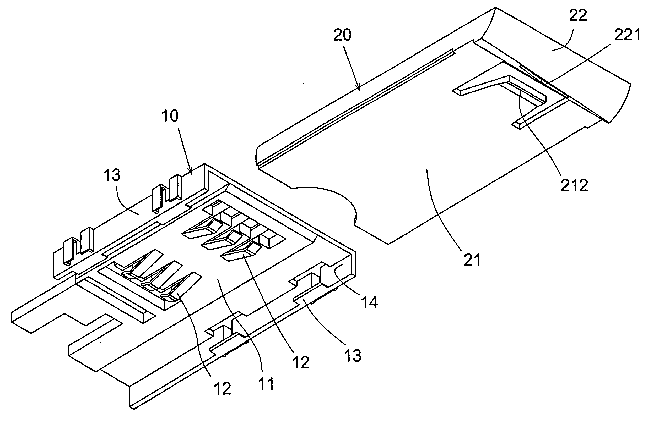
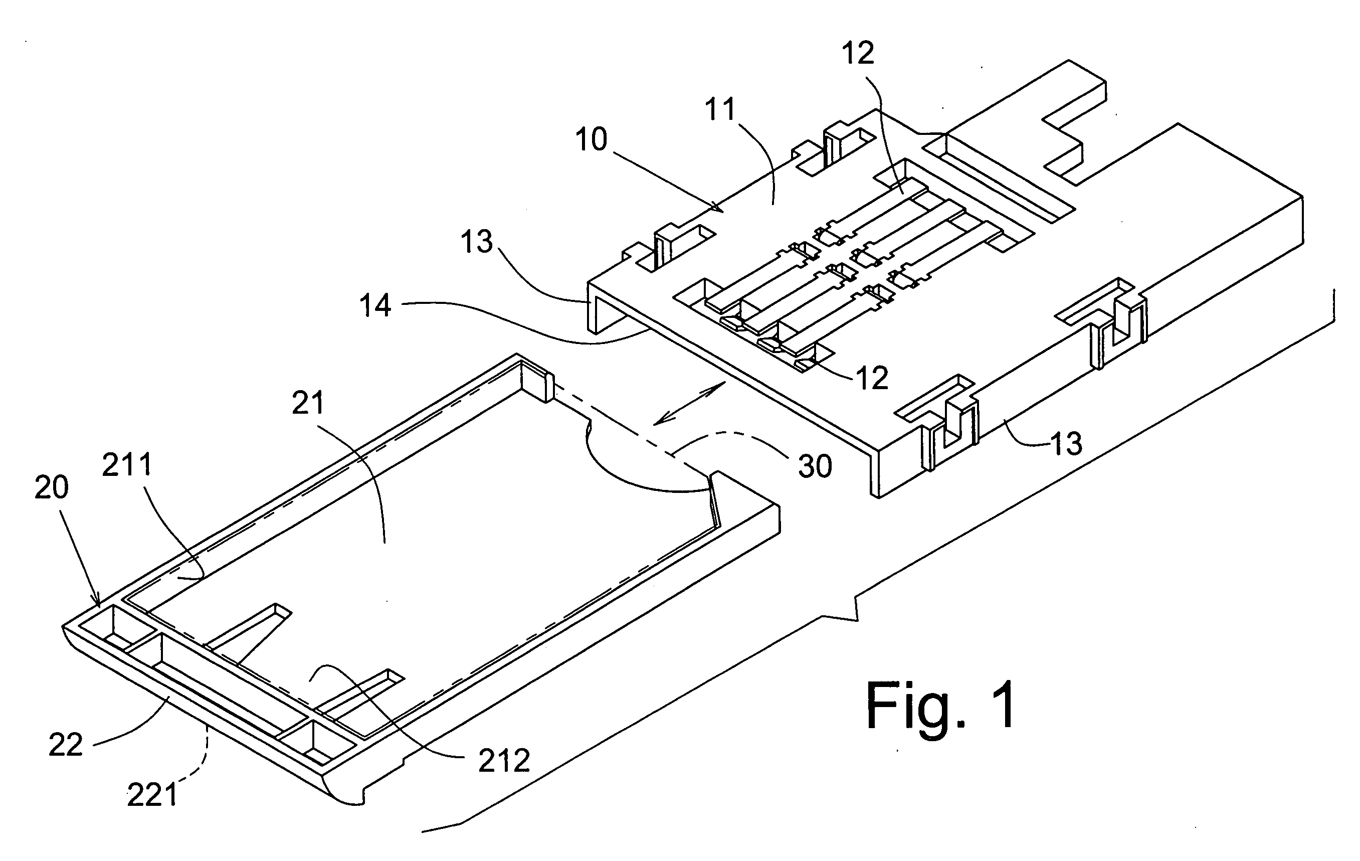
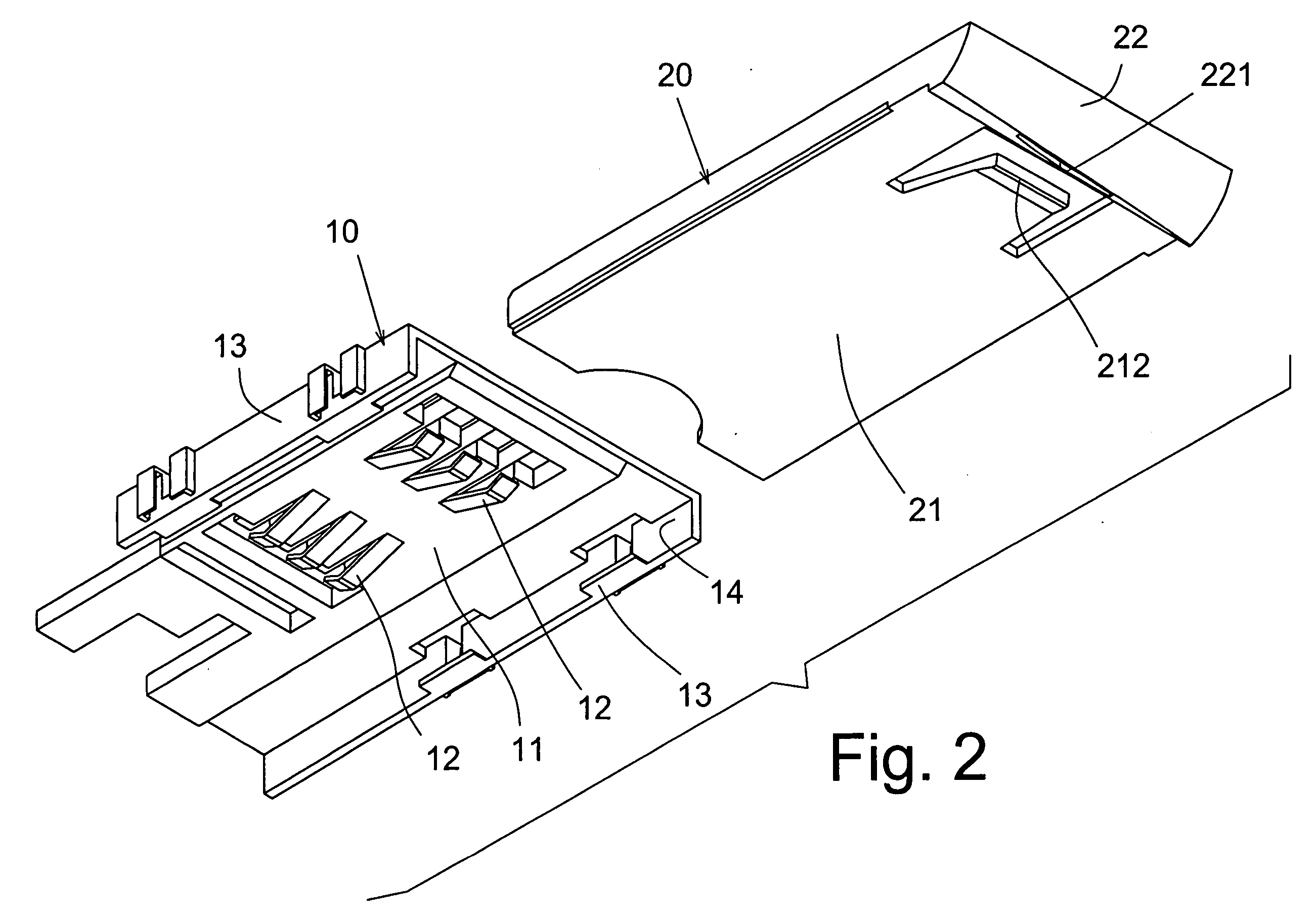
[0014] Please refer to FIGS. 1 to 6. The slide-out electronic card connector of the present invention includes a seat body 10. A slide cavity 14 is defined between two opposite sides of the seat body 10. Multiple terminals 12 are inlaid in the seat body 10. The slide-out electronic card connector of the present invention further includes a cartridge 20 snugly slidably disposed in the slide cavity 14 of the seat body 10. The cartridge 20 is formed with at least one electronic card receiving cavity 211 in which an electronic card 30 can be stably received. The cartridge 20 with the electronic card 30 can be slid into the seat body 10, whereby the electronic card 30 can be electrically connected with the terminals 12 in the seat body 10. The slide-out electronic card connector of the present invention is characterized in that the cartridge 20 has a resilient latch arm 212. When the cartridge 20 is slid into the seat body 10, the resilient latch arm 212 is correspondingly latched in a f...


PUM


Abstract

A slide-out electronic card connector includes a seat body and a slide cavity being defined between two opposite sides of the seat body. Multiple terminals are inlaid in the seat body. A cartridge snugly slidably disposed in the slide cavity of the seat body. An electronic card can be stably received in an electronic card receiving cavity of the cartridge and electrically connected with the terminals in the seat body when the cartridge with the electronic card is slid into the seat body. When the cartridge is slid into the seat body, a resilient latch arm is correspondingly latched in a fixing latch dent for preventing the cartridge from slipping out of the seat body. When a user outward draws the cartridge, the resilient latch arm is unlatched from the fixing latch dent, permitting the cartridge to be drawn out of the seat body and totally separated therefrom.

Description

BACKGROUND OF THE INVENTION [0001] 1. Field of the Invention [0002] The present invention is related to a slide-out electronic card connector, and more particularly to an electronic card connector in which the cartridge can be totally drawn out of the seat body without being suspended from the seat body. Therefore, a user can conveniently place the electronic card into the cartridge. Moreover, the breakage of the cartridge due to incautious collision can be avoided. [0003] 2. Description of the Prior Art [0004] In use of a cellular phone or a telecommunication equipment installed in a car, an electronic card must be inserted in the phone to achieve burglarproof and identification effect. In order to facilitate the installation and connection between the electronic card and the telecommunication equipment, my former invention entitled “memory card socket with drawer-type cartridge” now be issued as U.S. Pat. No. 6,805,589 discloses a memory card socket including a seat body having a ...

Claims


Application Information

Patent Timeline
Patent Type & Authority Applications(United States)
IPC IPC(8): H01R24/00
CPCG06K13/08H01R13/24H01R13/506H01R12/714Y10S439/946
Inventor LEE, IPSON
Owner ARGOSY RES
Why Eureka
Try Eureka