Directional antenna device

A technology of directional antennas and antenna units, applied in directions such as antennas, antenna arrays, diversity/multi-antenna systems, etc., can solve problems such as inability to work, and it is difficult to maintain stable transmission and reception.

Inactive Publication Date: 2006-12-20
SHIN NIPPON HERIKOPUTAA
View PDF0 Cites 12 Cited by
  • Summary
  • Abstract
  • Description
  • Claims
  • Application Information

AI Technical Summary

Problems solved by technology

[0003] Antenna elements that are directional transmit and receive radio waves well in one direction but barely work in the other
Therefore, radio waves cannot always be transmitted and received in an appropriate direction during mobile communication from the position of the side of the fixed entity used for reception
Therefore, as radio waves transmitted in a direction where transmission and reception are weak, only very weak radio waves can be transmitted and received, so that there is a problem that when interference waves (noise) of adjacent frequencies appear, It is difficult to maintain stable transmission and reception within the range of electromagnetic fields

Method used


Image

  • Directional antenna device
  • Directional antenna device
  • Directional antenna device

Examples


Embodiment 1

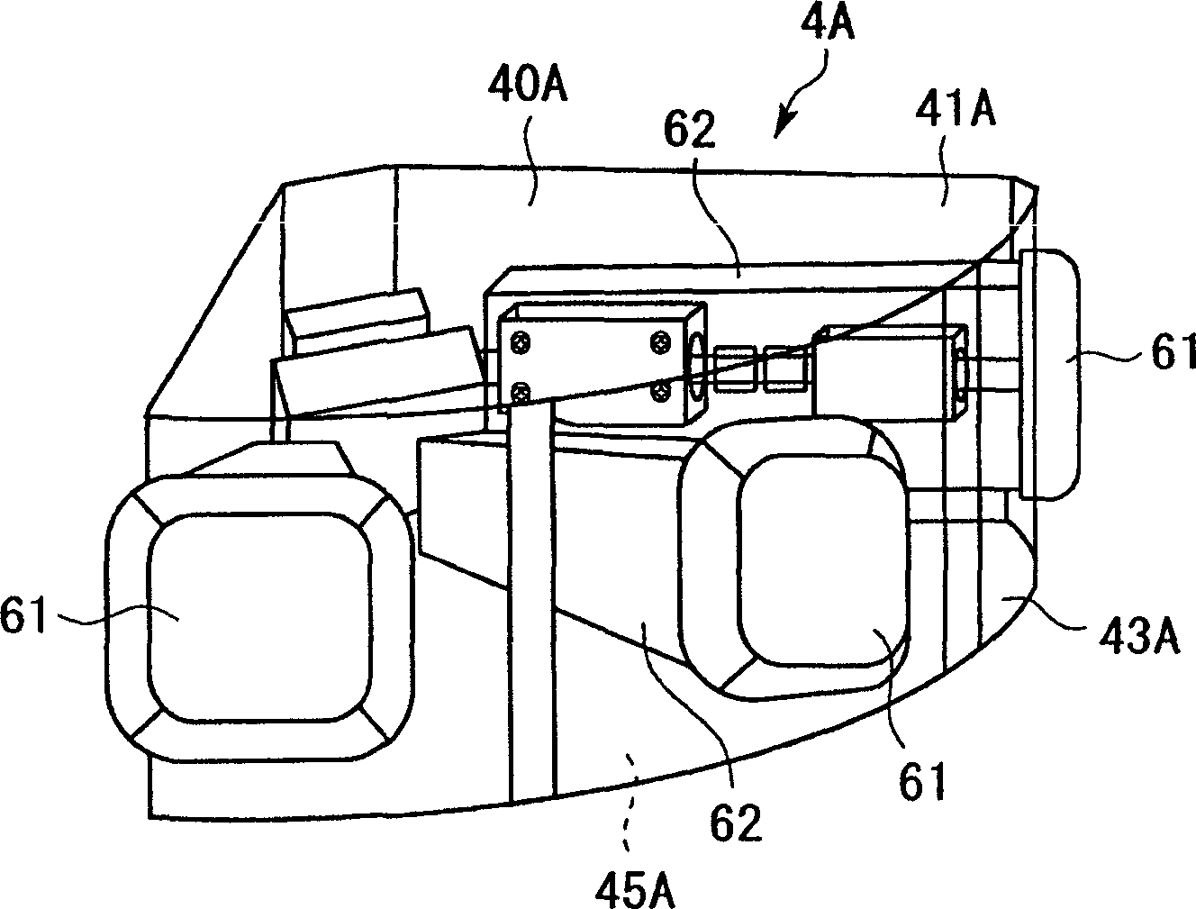
[0038] Below, based on image 3 and Figure 4 An embodiment 1 of the directional antenna device according to the present invention will be described, in which one flat antenna 61 is selected from three directional antennas (flat antennas) 61 .

[0039] In the directional antenna device according to Embodiment 1, the antenna unit 4A includes three flat antennas 61 arranged radially, such as Figure 4 shown in the floor plan. If it is assumed that the intersection of the axes of these three flat antennas 61 is a base point P, then viewed from this base point P, these flat antennas 61 are arranged in different directions at predetermined angular intervals (for example, 45°) on the air-to-ground horizontal plane .

[0040] Such as image 3 As shown, in the directional antenna device according to Embodiment 1, the antenna unit 4A includes a polyhedral housing 40A having a plurality of faces formed by a fan-shaped top face 41A, an air-to-ground flat face 43A, and a bottom face 4...

Embodiment 2

[0047] Below, based on Figure 5 and Figure 6 An embodiment 2 of the directional antenna device according to the present invention, in which one flat antenna 61 is selected from five directional antennas (flat antennas) 61 will be described.

[0048] In the directional antenna device according to Embodiment 2, the antenna unit 4B includes five flat antennas 61 arranged radially, such as Figure 6 shown in the floor plan. If it is assumed that the intersection of the axes of these five flat antennas 61 is a base point P, then viewed from the base point P, these flat antennas 61 are arranged in different directions at predetermined angular intervals (for example, 45°) on the air-to-ground horizontal plane .

[0049] Such as Figure 5 As shown, in the directional antenna device according to Embodiment 2, the antenna unit 4B includes a polyhedral housing 40B formed by a semicircular top surface 41B, an air-to-ground flat surface 43B, and a bottom surface 45B, and a mounting ...

Embodiment 3

[0056] Below, based on Figure 7 and Figure 8 An embodiment 3 of the directional antenna device according to the present invention will be described, in which one flat antenna 61 is selected from eight directional antennas (flat antennas) 61 .

[0057] In the directional antenna device according to Embodiment 3, the antenna unit 4C includes eight flat antennas 61 radially arranged, such as Figure 8 shown in the floor plan. If it is assumed that the axis crossing point of these eight flat antennas 61 is a base point P, then viewed from the base point P, these flat antennas 61 are arranged in different directions at predetermined angular intervals (for example, 45°) on the air-to-ground horizontal plane .

[0058] Such as Figure 7 As shown, in the directional antenna device described in Embodiment 3, the antenna unit 4C includes a polyhedral housing 40C composed of a circular top surface 41C, an air-to-ground flat surface 43C, and a bottom surface 45C, and a Antenna unit...


PUM


Abstract

There is provided a directional antenna device for receiving a radio wave of a microwave band transmitted from a communication unit arranged on a mobile body, by using an antenna unit having directivity arranged on a fixed body fixed to a predetermined position. The antenna unit includes: a plurality of directional antennas arranged with directivities in different directions; and a reception selection unit for selecting one of the directional antennas arranged in the transmission direction in which the radio wave reaches the fixed body, thereby receiving the radio wave. Thus, it is possible to provide a directional antenna device capable of performing stable transmission and reception without being affected by the relative position between the mobile body and the fixed body.

Description

technical field [0001] The present invention relates to a directional antenna device used in mobile communications, and more particularly, to a technology capable of reducing noise or reducing the influence of strong electromagnetic fields on adjacent frequencies for transmitting and receiving radio waves in the microwave frequency band . Background technique [0002] In recent years, mobile communication has been rapidly developed, and in mobile communication, one of sending and receiving communication, or both, is performed while in motion. Mobile communication is a communication system that operates (on a radio wave in the microwave frequency band) with very little electric power, which satisfies the following conditions: a station that allows radio broadcasting does not need to have a license as stipulated in Article 4 of the Radio Law. For example, a radio wave in the microwave frequency band is transmitted from a communication device (a communication unit) provided in...

Claims


Application Information

Patent Timeline
Patent Type & Authority Applications(China)
IPC IPC(8): H04B7/10H01Q3/24H01Q21/20H04B7/26
CPCH01Q3/24H01Q21/205H01Q21/00H04B7/10
Inventor 三浦寿夫
Owner SHIN NIPPON HERIKOPUTAA
Why Eureka
Try Eureka