Directional antenna device

Inactive Publication Date: 2007-03-15
SHIN NIPPON HERIKOPUTAA
View PDF5 Cites 12 Cited by
  • Summary
  • Abstract
  • Description
  • Claims
  • Application Information

AI Technical Summary

Benefits of technology

[0018] According to the directional antenna device of the present invention, the directional antenna device capable of performing stable transmission and

Problems solved by technology

Therefore, as a radio wave transmitted in a direction in which transmission and reception are poor, only a weak radio wave can be transmitted and received, and there has

Method used


Image

  • Directional antenna device
  • Directional antenna device
  • Directional antenna device

Examples


Example

Embodiment 1

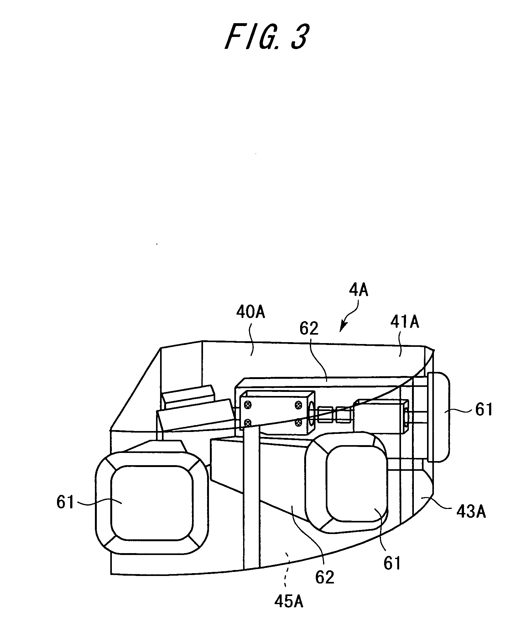
[0035] Next, in the directional antenna device according to the present invention, an embodiment 1 where one flat antenna 61 is selected from three directional antennas (flat antennas) 61 will be described based on FIGS. 3 and 4.

[0036] In the directional antenna device according to the embodiment 1, an antenna unit 4A includes radially arranged three flat antennas 61 as shown in a plan view of FIG. 4. When it is assumed that the intersection of axes of the three flat antennas 61 is a base point P, the flat antennas 61 are arranged at predetermined angular intervals (for example, of 45°) in different directions on an air-to-ground horizontal surface when viewed from the base point P.

[0037] In the directional antenna device according to the embodiment embodied 1, the antenna unit 4A includes, as shown in FIG. 3, a polyhedral polyhedron case 40A formed by a fan-shape top surface 41A, is an air-to-ground flat surface 43A, and a bottom surface 45A, and the antenna unit 4A ...

Example

Embodiment 2

[0043] Next, in the directional antenna device according to the present invention, an embodiment 2 where one flat antenna 61 is selected from five directional antennas (flat antennas) 61 will be described based on FIGS. 5 and 6.

[0044] In the directional antenna device according to the embodiment 2, an antenna unit 4B includes radially arranged five flat antennas 61 as shown in a plan view of FIG. 6. When it is assumed that the intersection of axes of the five flat antennas 61 is a base point P, the flat antennas 61 are arranged at predetermined angular intervals (for example, of 45°) in different directions on an air-to-ground horizontal surface when viewed from the base point P.

[0045] In the directional antenna device according to the embodiment 2, the antenna unit 4B includes, as shown in FIG. 5, a polyhedral case 40B formed by a semi-circular top surface 41B, an air-to-ground flat surface 43B, and a bottom surface 45B, and the antenna unit 4B is housed within the c...

Example

Embodiment 3

[0051] Next, in the directional antenna device according to the present invention, an embodiment 3 where one flat antenna 61 is selected from eight directional antennas (flat antennas) 61 will be described based on FIGS. 7 and 8.

[0052] In the directional antenna device according to the embodiment 3, an antenna unit 4C includes radially arranged eight flat antennas 61 as shown in a plan view of FIG. 8. When it is assumed that the intersection of axes of the eight flat antennas 61 is a base point P, the flat antennas 61 are arranged at predetermined angular intervals (for example, of 45°) in different directions on an air-to-ground horizontal surface when viewed from the base point P.

[0053] In the directional antenna device according to the embodiment 3, the antenna unit 4C includes, as shown in FIG. 7, a polyhedral case 40C formed by a circular top surface 41C, an air-to-ground flat surface 43C, and a bottom surface 45C, and the antenna unit 4C is housed within the cas...


PUM


Abstract

A directional antenna device for receiving a radio wave in a microwave band transmitted from a communication unit provided on a movable mobile body, by using an antenna unit having directivity and provided on a fixed body fixed to a predetermined position. The antenna unit includes: a plurality of directional antennas arranged with directivities in different directions; and reception selection unit for selecting one of the plurality of directional antennas arranged in the transmission direction in which the radio wave reaches the fixed body, thereby receiving the radio wave. Thus, it is possible to provide a directional antenna device capable of performing stable transmission and reception without being affected by the relative position between the mobile body and the fixed body.

Description

TECHNICAL FIELD [0001] The present invention relates to an antenna device having directivity, which is used in mobile communication, and more particularly to a technology of reducing a noise or the influence of an intense electric field at a near frequency for transmission and reception of a radio wave in a microwave band. RELATED ART [0002] In recent years, rapid development has been made on mobile communication, in which either one or both of transmission and reception perform communication while moving. The mobile communication is a communication system operating with a small electric power (at a radio wave in a microwave band), which satisfies the conditions allowing as a radio station that does not need a license as provided in the Radio Law, Article 4. For example, a radio wave in the microwave band, which is transmitted from a communication device (a communication unit) provided in a movable mobile body (a mobile station), is normally received or transferred by an antenna uni...

Claims


Application Information

Patent Timeline
IPC IPC(8): H01Q1/38H01Q3/24H01Q21/20H04B7/10H04B7/26
CPCH01Q21/205H01Q3/24H01Q21/00H04B7/10
Inventor MIURA, TOSHIO
Owner SHIN NIPPON HERIKOPUTAA
Why Eureka
Try Eureka