Apparatus and method for interference canceller in a high frequency receiver and transmitter
a technology of interference canceller and high frequency receiver, which is applied in the field of high frequency receiver to achieve the effect of reducing interference, stably receiving, and rapid removal of interference from transmission signals
- Summary
- Abstract
- Description
- Claims
- Application Information
AI Technical Summary
Benefits of technology
Problems solved by technology
Method used
Image
Examples
first exemplary embodiment
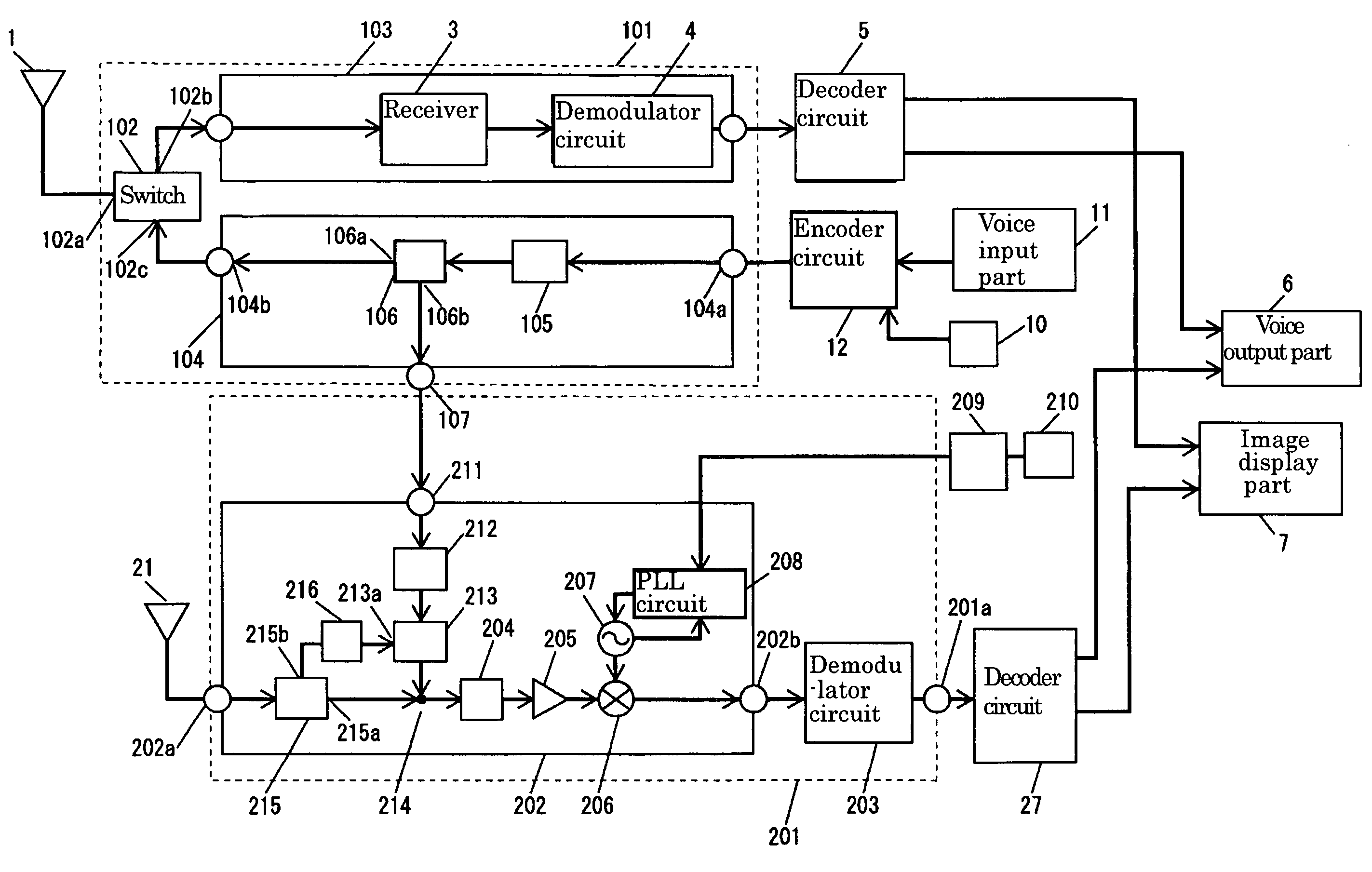
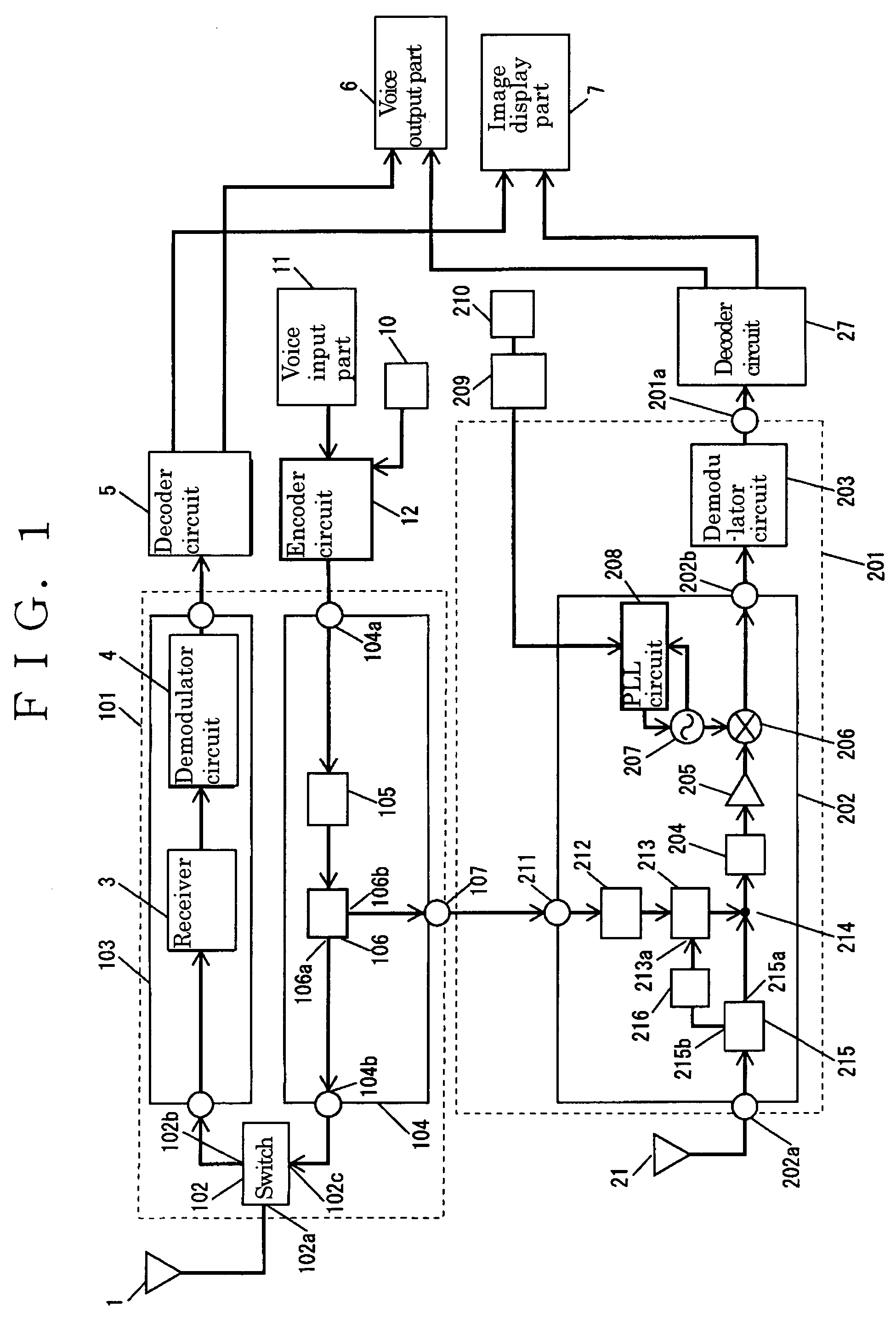
[0034]Hereinafter, a first exemplary embodiment is described with reference to drawings. FIG. 1 is a block diagram showing portable equipment in accordance with the first exemplary embodiment. The same references are given to the same elements as those described in FIG. 12 used in “Background Art” and description therefor is simplified.
[0035]To antenna 1 used as one of transmitting antennas, telephone part 101 is coupled. Telephone part 101 is prepared for transmitting and receiving a GSM mode telephone signal having a frequency of about 880 MHz. Furthermore, telephone part 101 includes antenna switch 102, receiving part 103 and transmitter 104. Antenna 1 is used for both transmitting and receiving signals.
[0036]To input-output terminal 102a of antenna switch 102, antenna 1 is coupled. To output terminal 102b, telephone receiver 3 is coupled. Antenna switch 102 switches a signal between transmission and reception. At the time of reception, a signal received by antenna 1 is output to...
second exemplary embodiment
[0068]Next, a second exemplary embodiment is described with reference to FIG. 3. FIG. 3 is a block diagram showing portable equipment. The same reference numerals are given to the elements as those in FIG. 1 and description therefor is simplified.
[0069]In TV tuner 300 in accordance with the second exemplary embodiment, instead of phase shifter 212 in accordance with the first exemplary embodiment, phase shifter 301 capable of changing phases is used. Phase shifter 301 changes a phase of a distributed transmission signal input to input terminal 301b in accordance with a voltage input to phase control terminal 301a.
[0070]Phase control terminal 301a is coupled to output terminal of control circuit 303 via control terminal 302 of TV tuner 300. Control circuit 303 is used as one of the phase controllers. Control circuit 303 is disposed in high frequency receiver 304 and coupled to control terminal 305a of level regulator 305 via control terminal 308 of TV tuner 300. To level control ter...
third exemplary embodiment
[0083]As described in the first exemplary embodiment, a phase shifter changing phases in a broad band generally has a complicated and large configuration and is expensive. Therefore, in equipment such as portable equipment in which portability is particularly preferential, it is difficult to employ such a configuration.
[0084]Then, in the third exemplary embodiment, instead of phase shifter 301 (FIG. 3) in accordance with the second exemplary embodiment, a phase shifter is configured by using phase shifter 501 (FIG. 5) capable of changing phases in a narrow frequency band.
[0085]Next, the third exemplary embodiment is described with reference to drawings. FIG. 5 is a block diagram showing a TV tuner. The same reference numerals are given to the same elements in FIG. 3 and the description therefor is simplified.
[0086]A receive signal input to input terminal 502a is input to a first input terminal of synthesizer 503 via directional coupler 215. An output signal from synthesizer 503 is i...
PUM
 Abstract
Description
Claims
Application Information
 - R&D
- Intellectual Property
- Life Sciences
- Materials
- Tech Scout
- Unparalleled Data Quality
- Higher Quality Content
- 60% Fewer Hallucinations
Browse by: Latest US Patents, China's latest patents, Technical Efficacy Thesaurus, Application Domain, Technology Topic, Popular Technical Reports.
© 2025 PatSnap. All rights reserved.Legal|Privacy policy|Modern Slavery Act Transparency Statement|Sitemap|About US| Contact US: help@patsnap.com


