Structure of carbon cloth

Inactive Publication Date: 2006-07-20
CHOU SHENG TENG
View PDF3 Cites 7 Cited by
  • Summary
  • Abstract
  • Description
  • Claims
  • Application Information

AI Technical Summary

Benefits of technology

[0005] The main purpose of the present invention is to provide an improved structure of carbon cloth. When weaving carbon cloth, color plastic thread or metallic yarn or glitter yarn of high retractility is directly added in either the carbon fiber warp or the carbon fiber weft under the principle of not

Problems solved by technology

However, although the method can add multiple colors to the cloth surface, it also has the following shortcomings: increased cost arising from

Method used


Image

  • Structure of carbon cloth
  • Structure of carbon cloth
  • Structure of carbon cloth

Examples


Embodiment Construction

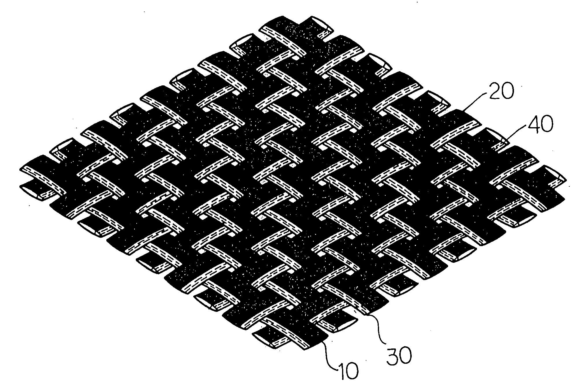
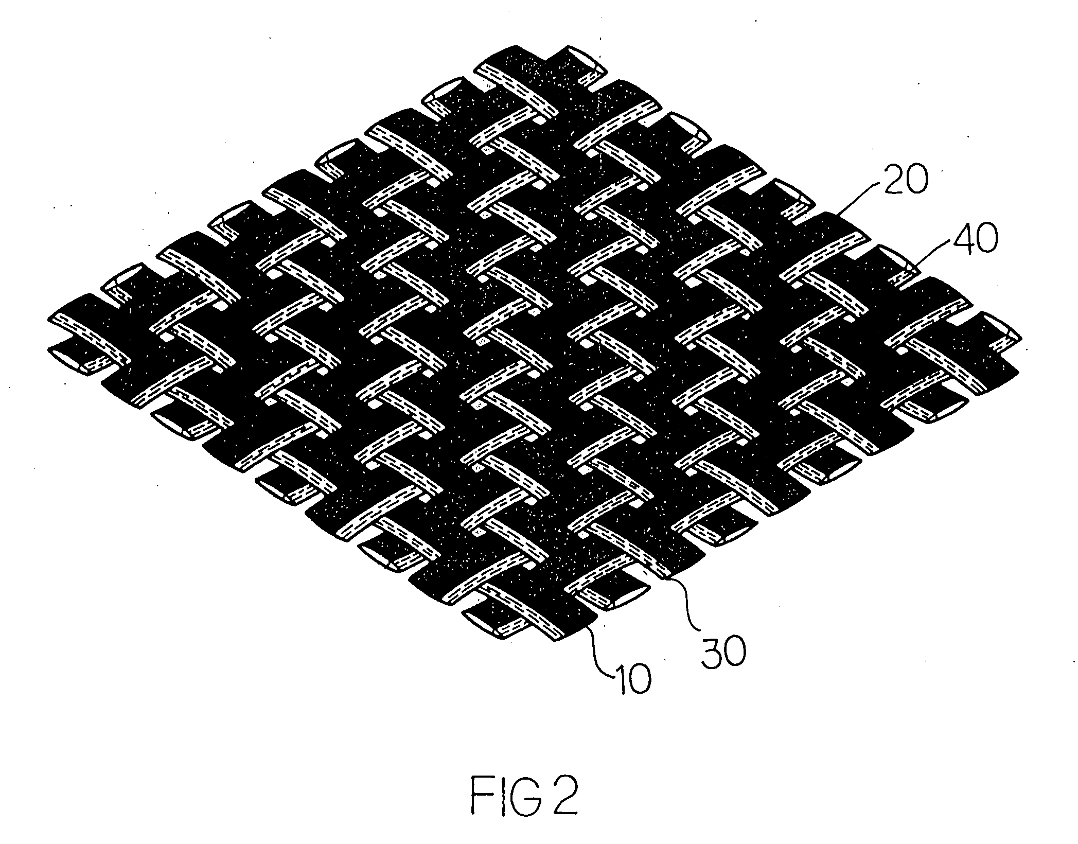
[0009] Firstly, please refer to FIG. 2. As shown in the figure, the present invention provides an improved structure of carbon cloth. That is, when weaving carbon cloth, color plastic thread 30 or metallic yarn 40, or glitter yarn of high retractility is skillfully added in the carbon fiber warp contexture 10 and carbon fiber weft contexture 20, thus making the cloth have a structure of rigidity and elasticity, and have bright colors as well as functions of reflecting, etc. Where, the foresaid plastic thread 30, or metallic yarn 40 or glitter yarn may be arranged nearby the outer side of the rigid carbon fiber warp or weft. Thus the surface of the carbon cloth is mainly made of jet black carbon fiber thread assisted with color plastic thread 30, metallic yarn 40 or glitter yarn of high retractility, better showing the bright colors of the plastic thread 30, metallic yarn 40 or glitter yarn. Since the section diameter of plastic thread is smaller than that of carbon fiber thread, the...


PUM

PropertyMeasurementUnit
Electric dipole momentaaaaaaaaaa
Diameteraaaaaaaaaa
Structureaaaaaaaaaa

Abstract

An improved structure of carbon cloth, wherein plain weave is used. Since carbon fiber thread is a kind of rigid materials and has no retractility, color plastic thread or metallic yarn of high retractility can be added in either the warp contexture or the weft contexture when weaving carbon. The ratio of carbon fiber thread to plastic thread or metallic yarn is 1800 D:50˜100 D. Carbon cloth made by using this method is more solid, wear resistant and not easy to loose, and can be provided with multiple colors and functions of reflecting, improving the shortcoming of the common structure that cloth can only have colors after being printed two times.

Description

FIELD OF INVENTION [0001] The present invention provides an improved structure of carbon cloth. BACKGROUND OF THE INVENTION [0002] When weaving carbon cloth, color plastic thread or metallic yarn is directly added in warp or weft. Since carbon fiber thread is jet black, the color of plastic thread or metallic yarn will be shown more obviously. Thus the carbon cloth has bright colors and improved functions such as reflecting, etc. [0003] Carbon cloth is widely applied in various industries. For example, it is often used as the coating of products such as battledore, bicycle frame, horn shell, shoe material, etc, so as to beautify the appearance and improve the value. As shown in FIG. 1, plain weave is utilized to interweave warp 100 and weft 200. Each warp 100 goes above or under the wefts 200 in turn, and two adjacent warps 100 are staggered one another. If a warp 100 goes under a weft 200, then the next warp 100 goes above the weft 200. Since carbon fiber thread is jet black, the c...

Claims


Application Information

Patent Timeline
IPC IPC(8): D03D15/00
CPCD03D15/00D03D15/0033D10B2101/12D10B2101/20D10B2401/061D10B2401/062Y10T442/313Y10T442/3008Y10T442/3114Y10T442/3089Y10T442/3293Y10T442/3976Y10T442/3065Y10T442/3179D03D15/54D03D15/275D03D15/283
Inventor CHOU, SHENG-TENG
Owner CHOU SHENG TENG
Why Eureka
Try Eureka