
Method and apparatus for arrhythmia detection in a medical device

Active Publication Date: 2006-07-20
MEDTRONIC INC
View PDF41 Cites 90 Cited by
  • Summary
  • Abstract
  • Description
  • Claims
  • Application Information

AI Technical Summary

Problems solved by technology

One potential problem associated with the sensing of the physiologic signal from the heart in both the transvenous systems and the subcutaneous systems relates to what is often referred to as “false positive” and “false negative” detections.

Method used


Image

  • Method and apparatus for arrhythmia detection in a medical device
  • Method and apparatus for arrhythmia detection in a medical device
  • Method and apparatus for arrhythmia detection in a medical device

Examples


Embodiment Construction

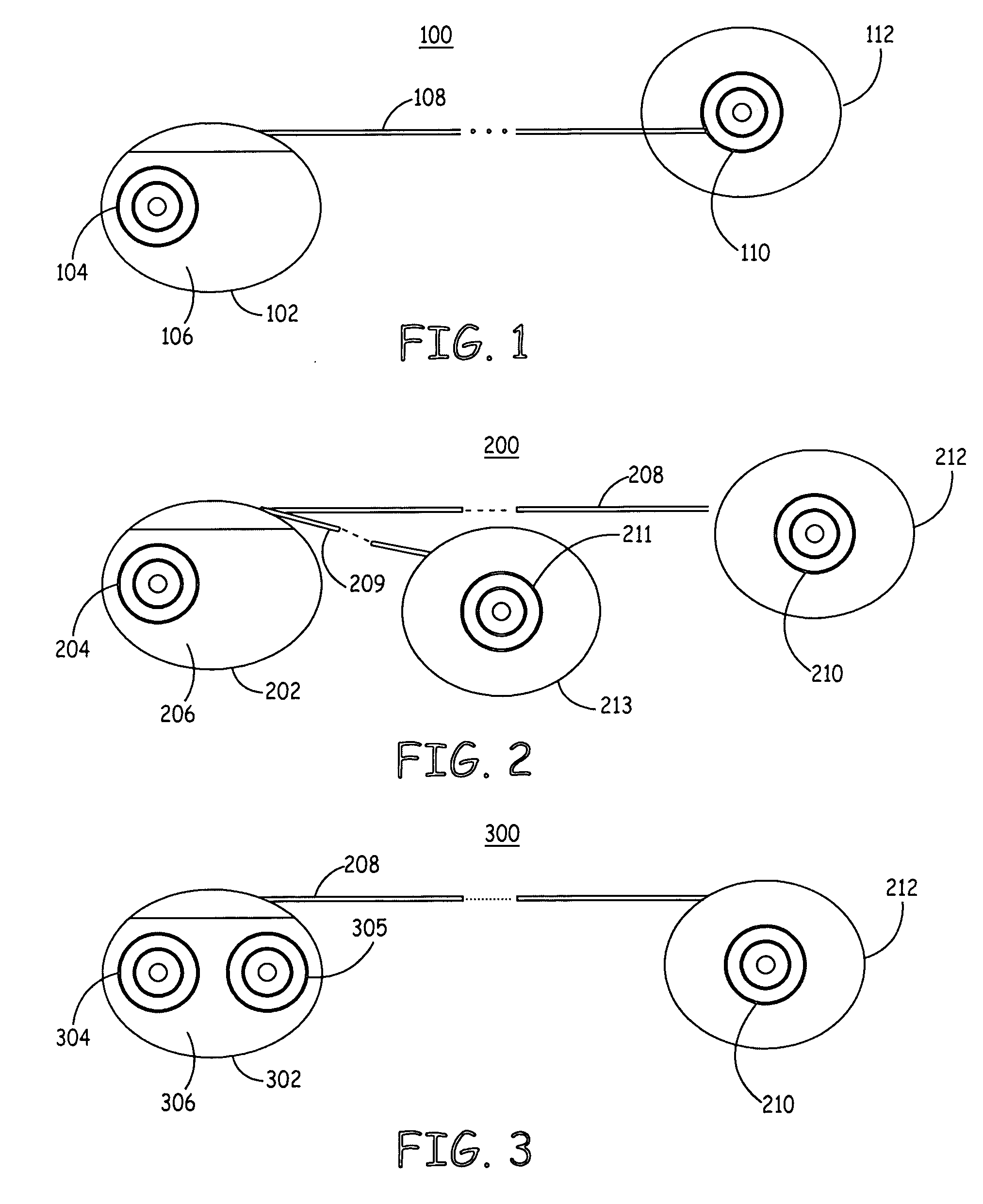
[0022]FIG. 1 is a schematic diagram of an exemplary medical device according to the present invention. As illustrated in FIG. 1, a medical device 100 according to an embodiment of the present invention, which may be an implantable cardioverter / defibrillator (ICD), for example, includes a housing 102 having an electrode 104 positioned along a side wall 106 of housing 102 that is intended to be directed inward towards a heart of a patient when housing is positioned subcutaneously within the patient, as will be described in detail below. Housing 102 is coupled to a subcutaneous lead 108 carrying conventional conductors (not shown) extending therethrough to electrically couple circuitry located within housing 102 to an electrode 110 positioned on an insulated patch 112 positioned subcutaneously within the patient so that electrode 110 is directed towards the patient's heart.

[0023] According to the present invention, electrodes 104 and 110 are formed using Laplacian electrodes that are ...


PUM


Abstract

A method and device for detecting arrhythmias in a patient that includes electrodes positioned subcutaneously within the patient, a microprocessor, coupled to the electrodes, determining one of a sequence of the sensing of cardiac signals by the electrodes and a duration between the sensing of cardiac signals by the electrodes, and control circuitry delivering a therapy in response to one of the determined sequence and the determined duration.

Description

FIELD OF THE INVENTION [0001] The present invention relates generally to medical devices, and, more particularly, to a method and apparatus for sensing and detecting arrhythmias in a medical device. BACKGROUND OF THE INVENTION [0002] Implantable medical devices (IMDs) have many functions including the delivery of therapies to cardiac patients, neuro-stimulators, muscular stimulators, and others. For purposes of this application reference will be made only to implantable cardiac devices, it being understood that the principles herein may have applicability to other implantable medical devices as well. [0003] An implantable cardiac device (ICD) may be a device commonly referred to as a pacemaker, which is used to stimulate the heart into a contraction if the sinus node of the heart is not properly timing, or pacing, the contractions of the heart. Modern cardiac devices also perform many other functions beyond that of pacing. For example, some cardiac devices may also perform therapies...

Claims


Application Information

Patent Timeline
IPC IPC(8): A61N1/36A61B5/296
CPCA61B5/0408A61N1/05A61N1/3622A61N1/3702A61N1/3756A61N1/3925A61N1/3956A61N1/3987A61B5/25A61B5/28
Inventor MITRANI, PAUL D.TARJAN, PETER P.GILLBERG, JEFFREY M.
Owner MEDTRONIC INC
Learn More