Engine output controller

a technology of output controller and engine, which is applied in the direction of electrical control, program control, instruments, etc., can solve the problems of engine driving according to a preset output curve deteriorating fuel consumption and fuel consumption deterioration, so as to reduce engine output, prevent wasteful output, and reliably improve fuel consumption

Inactive Publication Date: 2006-07-20
KOMATSU LTD
View PDF24 Cites 40 Cited by
  • Summary
  • Abstract
  • Description
  • Claims
  • Application Information

AI Technical Summary

Benefits of technology

The present inventors have developed a system for controlling the power input during construction machines by adjusting certain parameters based upon factors like ground speeds and loads being lifted at different times. This helps optimize energy usage efficiency and reduces emissions compared to traditional methods where all these variables were fixed regardless. Additionally, they suggest switching between multiple operating states (lower/upper) based on specific conditions rather than just one setting. By doing so, it can achieve better control over both high torque and low duty cycles, resulting in increased productivity. Overall, their technical effect includes efficient utilization of resources and reduction of environmental pollution caused by excessive exhaustion rates due to heavy lifting operations.

Problems solved by technology

The technical problem addressed in this patent text is to reduce fuel consumption in construction machines or similar machines that use diesel engines by adjusting the engine output curve based on the load and speed range, so that the engine operates at a lower output in a low-load operation mode. This is done to avoid unnecessary speed increases and reduced fuel consumption.

Method used


Image

  • Engine output controller
  • Engine output controller
  • Engine output controller

Examples


first embodiment

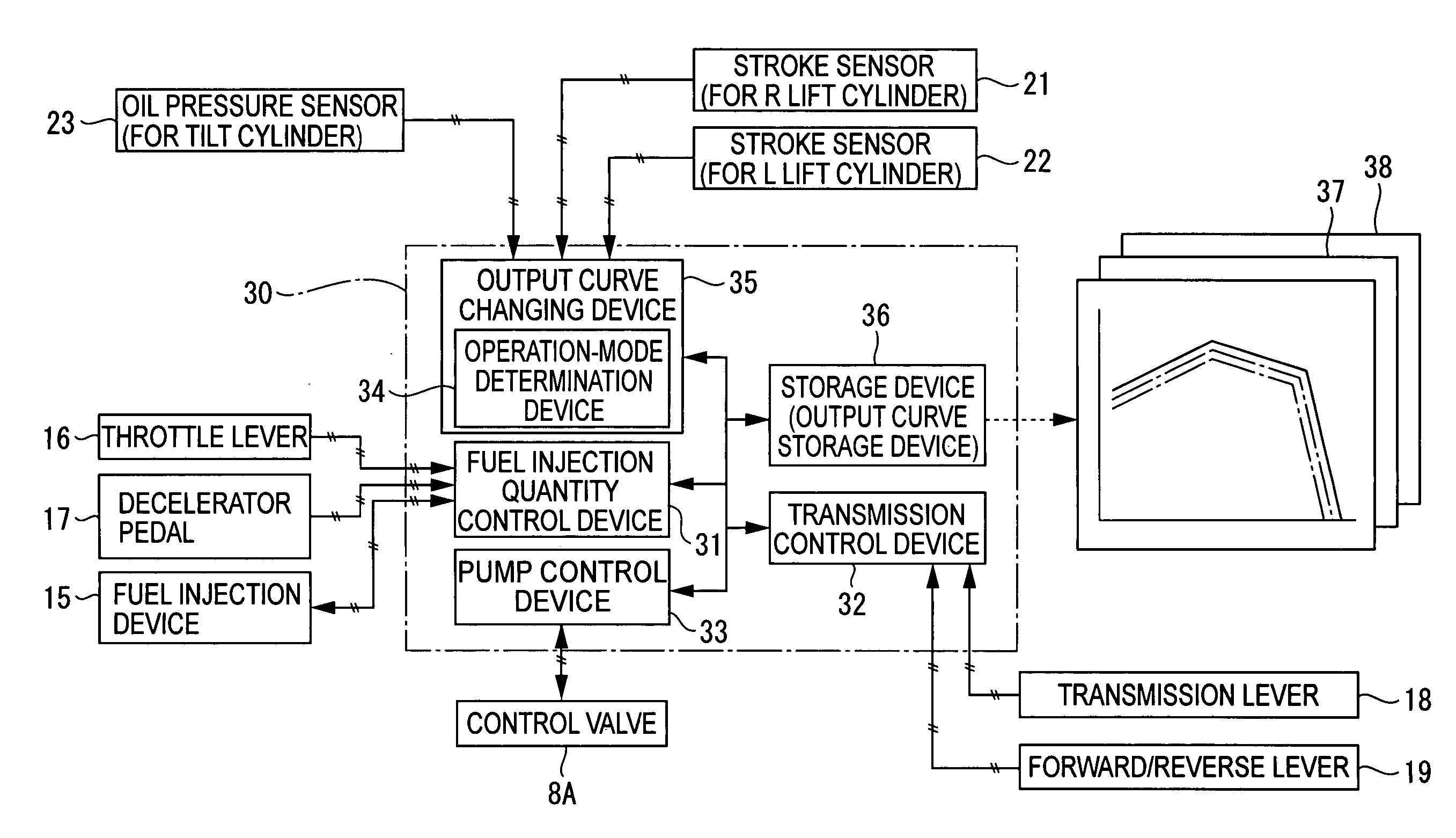
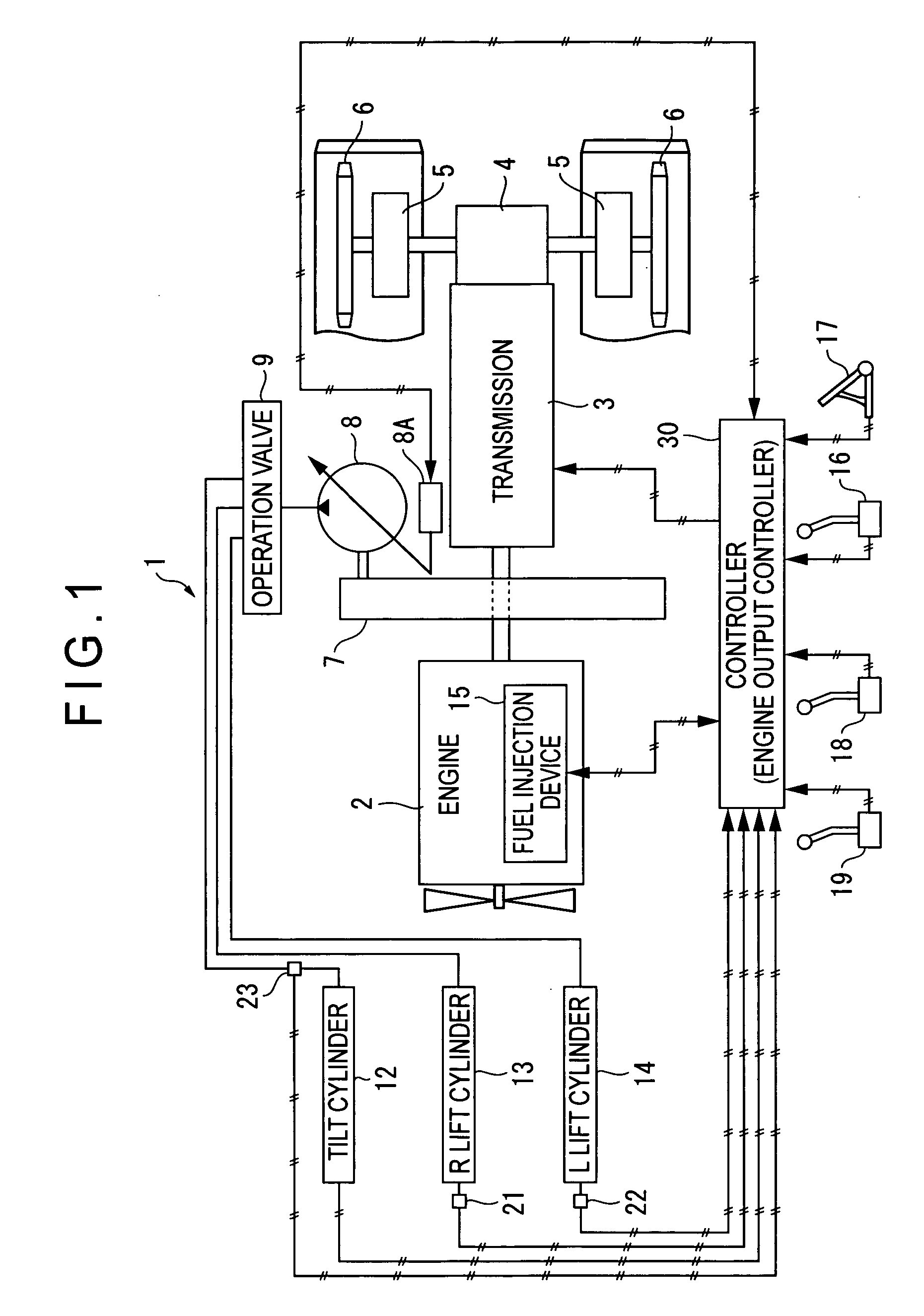
[0048]FIG. 1 is a schematic diagram showing a bulldozer 1 equipped with a controller (engine output controller) 30 according to a first embodiment of the present invention.

[0049] The bulldozer 1 is arranged to drive a transmission 3 directly by the output of diesel engine 2 and to drive a sprocket 6 through a steering clutch 4 and a final reduction gear unit 5.

[0050] However, the drive system is not limited to the above. The drive system may be a torque flow system to transmit an output of an engine 2 to the transmission 3 through a torque converter; a hydro-shift system to transmit an output of an engine 2 to the transmission 3 through a damper and a joint; a hydro-static system to convert an output of an engine 2 into a liquid energy once by a hydraulic pump, return the liquid energy again to a mechanical energy by a hydraulic motor and transmit the mechanical energy to the sprocket 6 through the final reduction gear unit 5; and a hydro-mechanical system to combine mechanical ef...

second embodiment

[0087] A schematic diagram of a motor grader 40 equipped with a controller 30 according to a second embodiment of the present invention is shown in FIG. 8.

[0088] It should be noted that in FIG. 8, the same configurations as in the first embodiment are shown in the same codes and the detailed descriptions thereof are omitted. The same manner is adopted in a third embodiment described hereinafter.

[0089] A motor grader 40 is arranged such that an output from the engine 2 is transmitted through a torque converter 41 to the transmission 3 and further transmitted to rear wheels 44 through a differential gear 42, a final reduction gear unit 5 and a tandem drive device 43. In such a motor grader 40, the hydraulic pump 8 is driven via the PTO 7 to distribute oil pressure to each working unit by an operation valve 9.

[0090] Working units of the motor grader 40 include a scarifier cylinder 45, an R (right) blade lift cylinder 46, an L (left) blade lift cylinder 47, a draw-bar side shift cyli...

third embodiment

[0109] A schematic diagram of a hydraulic excavator 60 equipped with a controller 30 according to a third embodiment of the present invention is shown in FIG. 12.

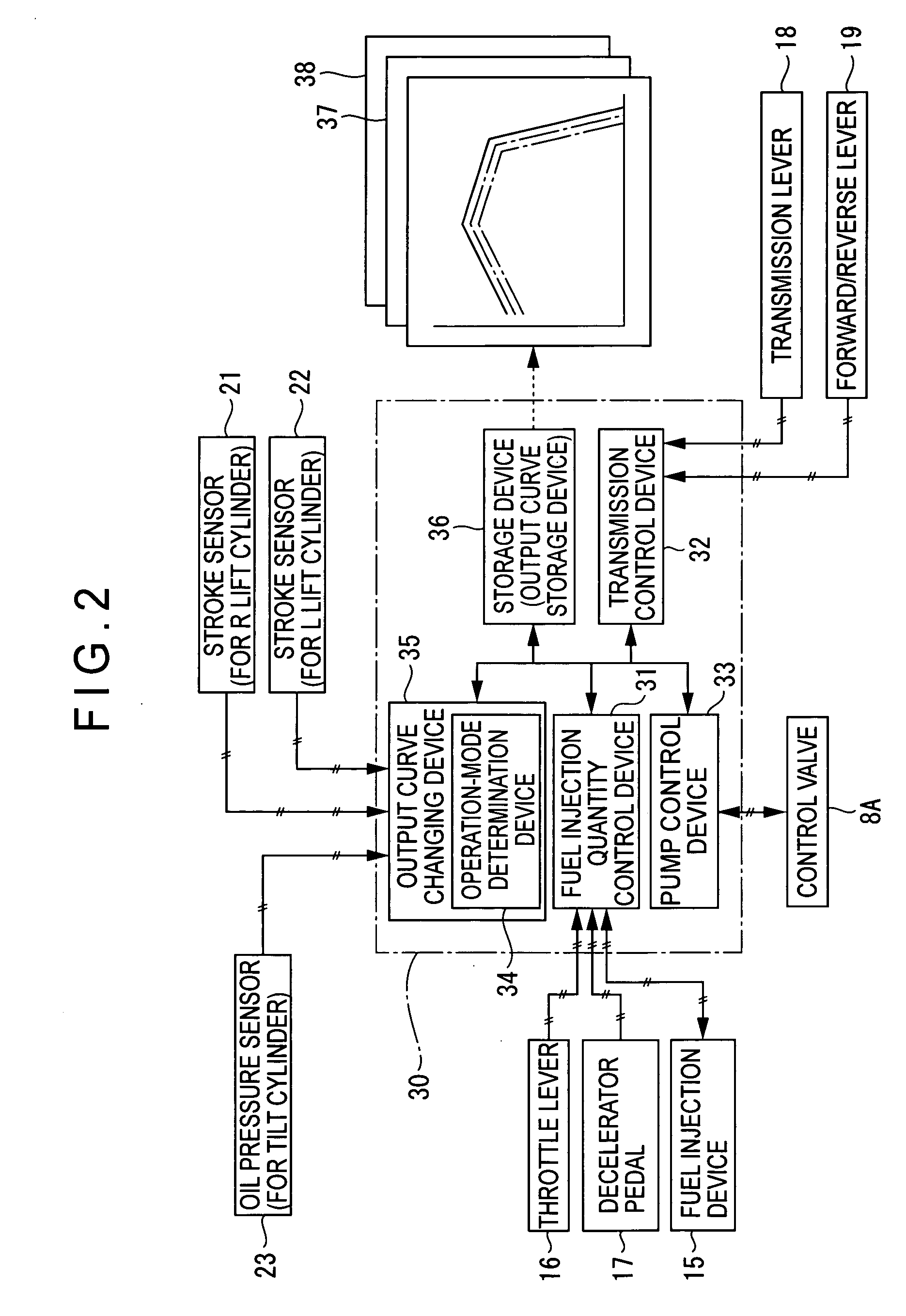
[0110] A hydraulic excavator 60 is arranged such that an F (front) hydraulic pump 8f and an R (rear) hydraulic pump 8r are driven by outputs of the engine 2 and oil pressure is distributed to each working unit by the operation valve 9. Each swash-plate angle of the hydraulic pump 8f and 8r is controlled by each control valve 8Af and 8Ar respectively. Further, the hydraulic excavator 60 includes a fuel dial 61, and based on a throttle signal from the fuel dial 61, the fuel injection device 15 is controlled by the fuel injection quantity control device 31 (FIG. 2) of the controller 30.

[0111] The working units of the hydraulic excavator 60 include a bucket cylinder 62, an arm cylinder 63, a boom cylinder 64, a turning motor 65 and a running motor 66. In order to detect a state of oil pressure supplying to the above, oil pres...


PUM


Abstract

An engine output controller provided in a bulldozer includes an output curve storage device storing a plurality of output curves of an engine and an output curve changing device selecting and shifting to one of the plurality of output curves. The output curve changing device, when a pressure of a blade tilt cylinder is equal to or more than a predetermined value, calls and shifts to a higher output curve from the output curve storage device. When an oil pressure is supplied to the tilt cylinder to tilt a blade and an operation is performed without reducing a soil pressing speed in this condition, the output curve changing device shifts the current output curve to the higher output curve to drive the engine. However, in many other cases, the output curve is automatically switched to a lower output curve to reduce an output of the engine. Thus, the fuel consumption is improved.

Description


Claims


Application Information

Patent Timeline
Owner KOMATSU LTD
Why Eureka
Try Eureka