Structured combustion chamber for use in engine

Active Publication Date: 2006-11-30
MITSUBISHI MOTORS CORP
View PDF12 Cites 3 Cited by
  • Summary
  • Abstract
  • Description
  • Claims
  • Application Information

AI Technical Summary

Benefits of technology

[0014] The present invention has been developed in consideration of these problems, and it is therefore an object of the invention to provide a structured combustion chamber of an engine capable of improving the combustion stability, exhaust gas performance and fuel consumption of an engine and of suppressing a decrease in engine output, particularly, the degradation of the full-opening performance of the engine.
[0015] For this purpose, in accordance with the present invention, there is provided a structured combustion chamber for use in an engine, comprising a cylinder head including an intake hole portion which makes a communication between an intake port and a combustion chamber and an exhaust hole portion which makes a communication between an exhaust port and the combustion chamber, an intake valve for opening and closing the intake hole portion, a continuous variable valve lift mechanism for lifting the intake valve in a stepless fashion, and a flow promoting device made to promote a motion of an air current in the combustion chamber when a quantity of lift of the intake valve driven by the continuous variable valve lift mechanism is small and made to suppress a decrease in flow rate of an intake air coming through the intake hole portion into the combustion chamber when the quantity of lift of the intake valve driven by the continuous variable valve lift mechanism reaches a maximum.
[0016] This structure can contribute to the promotion of suction flow in a combustion chamber, thereby improving the combustion stability, exhaust gas performance and fuel consumption, even in the case of a small lift quantity of an intake valve and a small suction quantity into a combustion chamber.
[0017] In addition, in a case in which the lift quantity of the intake valve is at a maximum, that is, even when a demand exists for the engine to produce the maximum output torque, the decrease in quantity of suction flow into the combustion chamber is suppressible to the utmost, thus suppressing the decrease in engine output.

Problems solved by technology

However, the formation of the wall portion based on such a consideration counteracts the suction flow into the combustion chamber, which additionally creates a problem of holding down the torque outputted from the engine.
Furthermore, in the continuous variable valve lift mechanism, the realization of delicate suction quantity control requires securing the performance in a high valve lift condition while enhancing the suction flow in a low valve lift condition.
Accordingly, in a case in which a wall portion is formed for the purpose of enhancing the suction flow in the case of the valve driving by the low lift cam as written in the patent document 1, no consideration is given to the engine performance in a high valve lift condition, which leads to considerably hindering the suction flow to the combustion chamber.
Therefore, in such a continuous variable valve lift mechanism, the formation of a wall portion disclosed in the patent document 1 extremely degrades the full-opening performance of the engine.

Method used


Image

  • Structured combustion chamber for use in engine
  • Structured combustion chamber for use in engine
  • Structured combustion chamber for use in engine

Examples


first embodiment

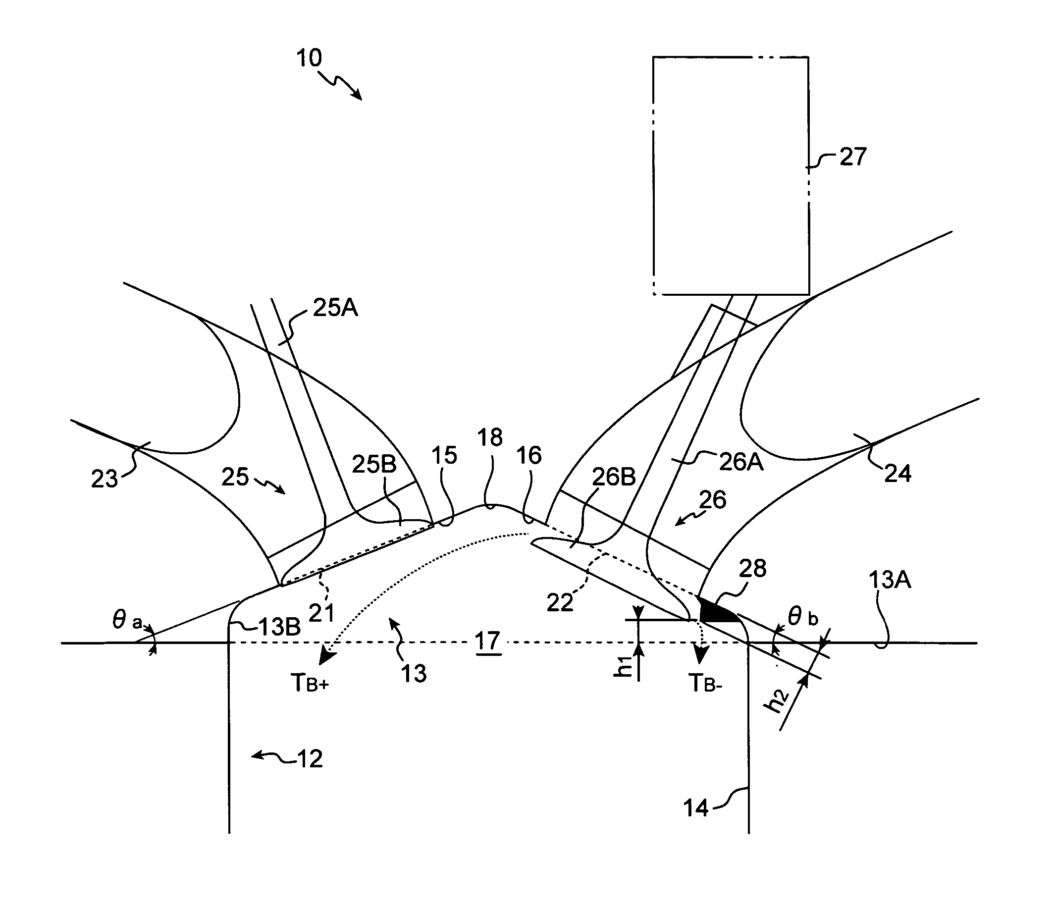
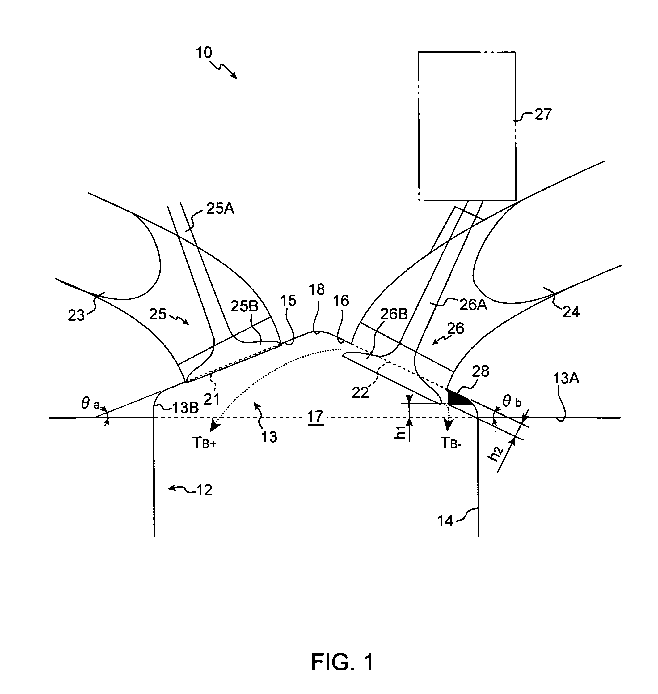
[0030] With reference to the drawings, a description will be given hereinbelow of a structure of a combustion chamber of an engine according to the present invention. FIG. 1 is a cross-sectional view illustratively showing a structure of a combustion chamber thereof, FIG. 2 is a plan view illustratively showing a cylinder head when viewed from a cylinder block side, FIG. 3 is an graphic diagram illustratively showing the relationship between the degree of air flow and a quantity of lift of an intake valve in the combustion chamber, and FIG. 4 is a graphic diagram illustratively showing the relationship between a suction flow into the combustion chamber and a quantity of lift of an intake valve.

[0031] As shown in FIGS. 1 and 2, an engine 10 is mainly made up of a cylinder block 12 and a cylinder head 13. A cylinder is formed in the cylinder block 12, and an exhaust side slope (first inclination surface) 15 and an intake side slope (second inclination surface) 16 are formed in the cyl...

second embodiment

[0088] Yet additionally, the one end portions 48A and 48A of the shroud 48 lies on the straight line L2 connecting the central points C2 and C2 of the intake valves 46 and 46 and are formed between the intake hole portions 42 and 42, while the other end portions 48B and 48B thereof reside on the intake side slope 36, at the outer edge portions of the intake hole portions 42 and 42 and in the vicinity of the cylinder lower end plane 33A.

[0089] Moreover, a lower edge portion 48E of the shroud 48 is made to have the same height as those of the lower end planes 33A and 33C.

[0090] Still moreover, as shown in FIG. 6, the shroud 48 is formed such that the height (see arrows h3 in FIG. 6) relative to the intake side slope 36 is approximately 1.0 millimeter. Incidentally, this height h3 is not limited to approximately 1.0 millimeter, but this height h3 can properly be changed provided that it is below 2.0 millimeters.

[0091] The structure of the engine combustion chamber according to the s...


PUM


Abstract

In a structured combustion chamber for an engine, comprising a cylinder head including an intake hole portion which makes a communication between an intake port and a combustion chamber and an exhaust hole portion which makes a communication between an exhaust port and the combustion chamber, an intake valve for opening and closing the intake hole portion, and a continuous variable valve lift mechanism for lifting the intake valve in a stepless fashion, a flow promoting device is provided to promote a motion of an air current in the combustion chamber when a quantity of lift of the intake valve driven by the continuous variable valve lift mechanism is small and further to suppress a decrease in flow rate of an intake air coming through the intake hole portion into the combustion chamber when the quantity of lift of the intake valve driven by the continuous variable valve lift mechanism reaches a maximum.

Description

BACKGROUND OF THE INVENTION [0001] (1) Field of the Invention [0002] The present invention relates to a structured combustion chamber for use in an engine. [0003] (2) Description of the Related Art [0004] So far, in an engine mounted on an automobile, there has been known a mechanism which can vary a timing of lift (that is, phase based on rotation of a crankshaft) or quantity of lift of an intake valve or exhaust valve. This mechanism, which has already been put to practical use, is referred to as a valve operating mechanism or variable valve lift mechanism and is designed to improve the fuel consumption in a low rotation region while securing the engine output in a high rotation region. [0005] As a document describing one example of a technology related to this valve operating mechanism, there is a technique disclosed in Japanese Patent Laid-Open No. 2004-293483 (patent document 1). This patent document 1 discloses a technique capable of varying the quantity of lift of an intake v...

Claims


Application Information

Patent Timeline
IPC IPC(8): F02B31/00F01L1/34F02N3/00
CPCY02T10/146F01L3/06F02D13/0223F02B2275/48F01L13/00Y02T10/18Y02T10/12
Inventor YOSHIKAWA, SATOSHI
Owner MITSUBISHI MOTORS CORP
Why Eureka
Try Eureka