Travel Drive System for Work Vehicle, Work Vehicle, and Travel Drive Method

a technology for work vehicles and drive devices, applied in the direction of gas pressure propulsion mounting, rotary clutches, jet propulsion mounting, etc., can solve the problems of fuel consumption degradation, achieve the effect of reducing the proportion of engine output distributed to the hst drive device, efficient operation, and increasing fuel economy

Inactive Publication Date: 2010-02-11
NIHON KENKI CO LTD
View PDF10 Cites 11 Cited by
  • Summary
  • Abstract
  • Description
  • Claims
  • Application Information

AI Technical Summary

Benefits of technology

[0014]According to the present invention, a HST drive device can be efficiently operated so as to increase fuel economy because a first drive wheel and a second drive wheel are driven by the HST drive device and an electric motor respectively and, as the detected vehicle speed increases, the proportion of output of the engine distributed to the HST drive device is reduced.

Problems solved by technology

There has been a problem which results from characteristics of an HST, that is, even though the travel drive system exerts large tractive force during low-speed running, fuel consumption deteriorates due to a gear transmission loss during high-speed running.

Method used


Image

  • Travel Drive System for Work Vehicle, Work Vehicle, and Travel Drive Method
  • Travel Drive System for Work Vehicle, Work Vehicle, and Travel Drive Method
  • Travel Drive System for Work Vehicle, Work Vehicle, and Travel Drive Method

Examples


first embodiment

[0024]A travel drive system according to the first embodiment of the present invention is now described in reference to FIGS. 1 to 7.

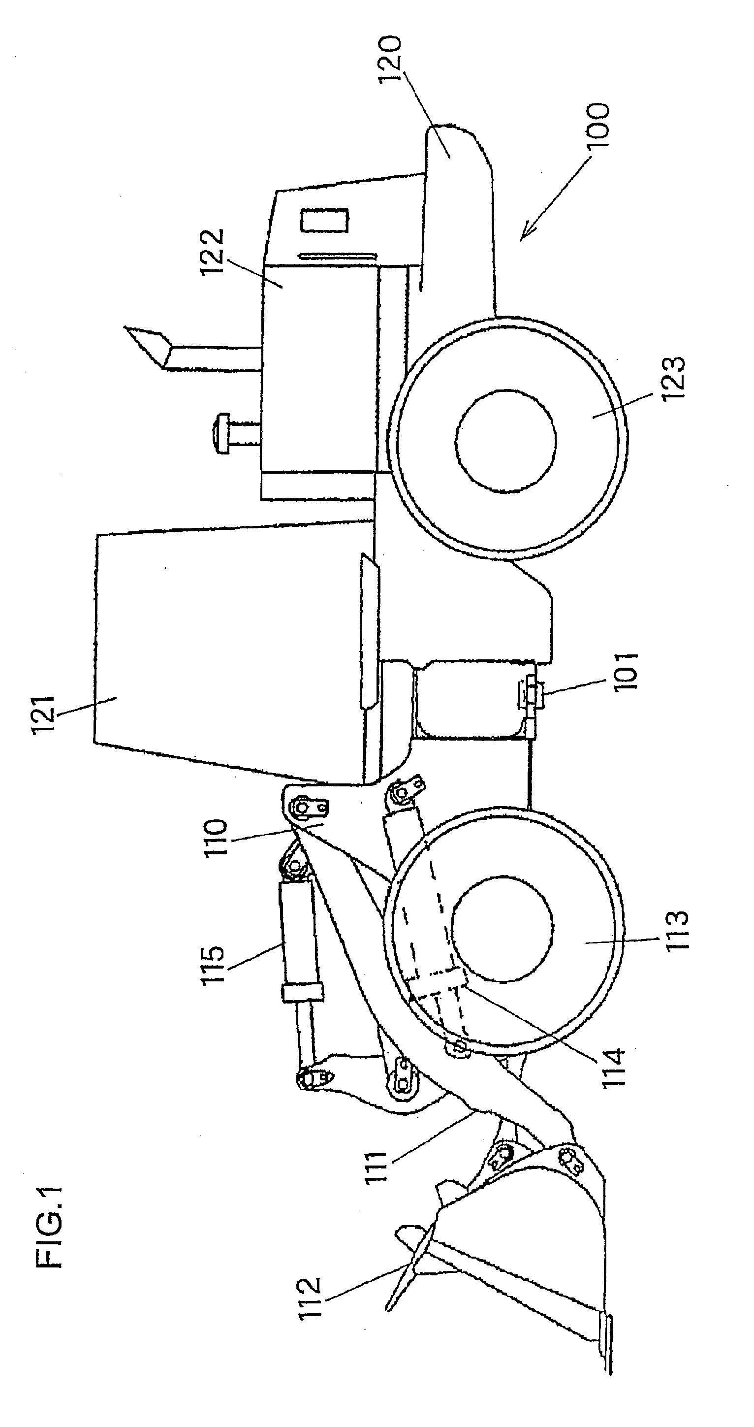
[0025]FIG. 1 is a side view of a wheel loader, an example of a work vehicle to which the travel drive system according to the first embodiment is applied. A wheel loader 100 includes a front body 110 which is provided with an arm 111, a bucket 112, front wheels 113, etc., and a rear body 120 which is provided with an operator's cab 121, an engine compartment 122, rear wheels 123, etc. The arm 111 is driven to elevate by an arm cylinder 114. The bucket 112 is driven to dump or crowd by a bucket cylinder 115. The front body 110 and the rear body 120 are rotatably connected with each other with a center pin 101. The front body 110 turns right and left relative to the rear body 120 by expansion and contraction of a steering cylinder (not shown herein). The front wheels 113 and the rear wheels 123 are driven by the travel drive system explained below for th...

second embodiment

[0053]The travel drive system in accordance with the second embodiment of the present invention is now explained in reference to FIGS. 8 and 9.

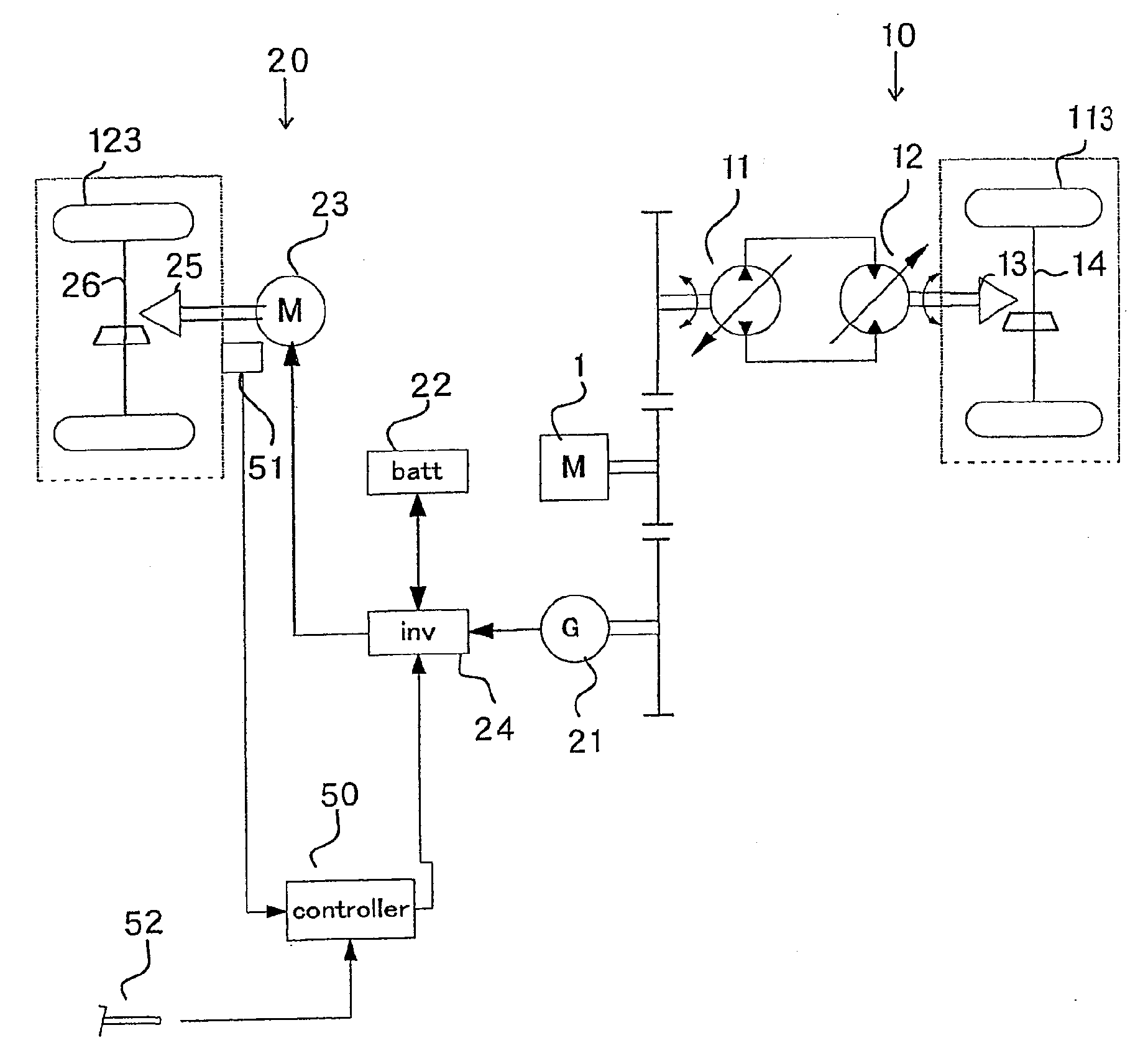
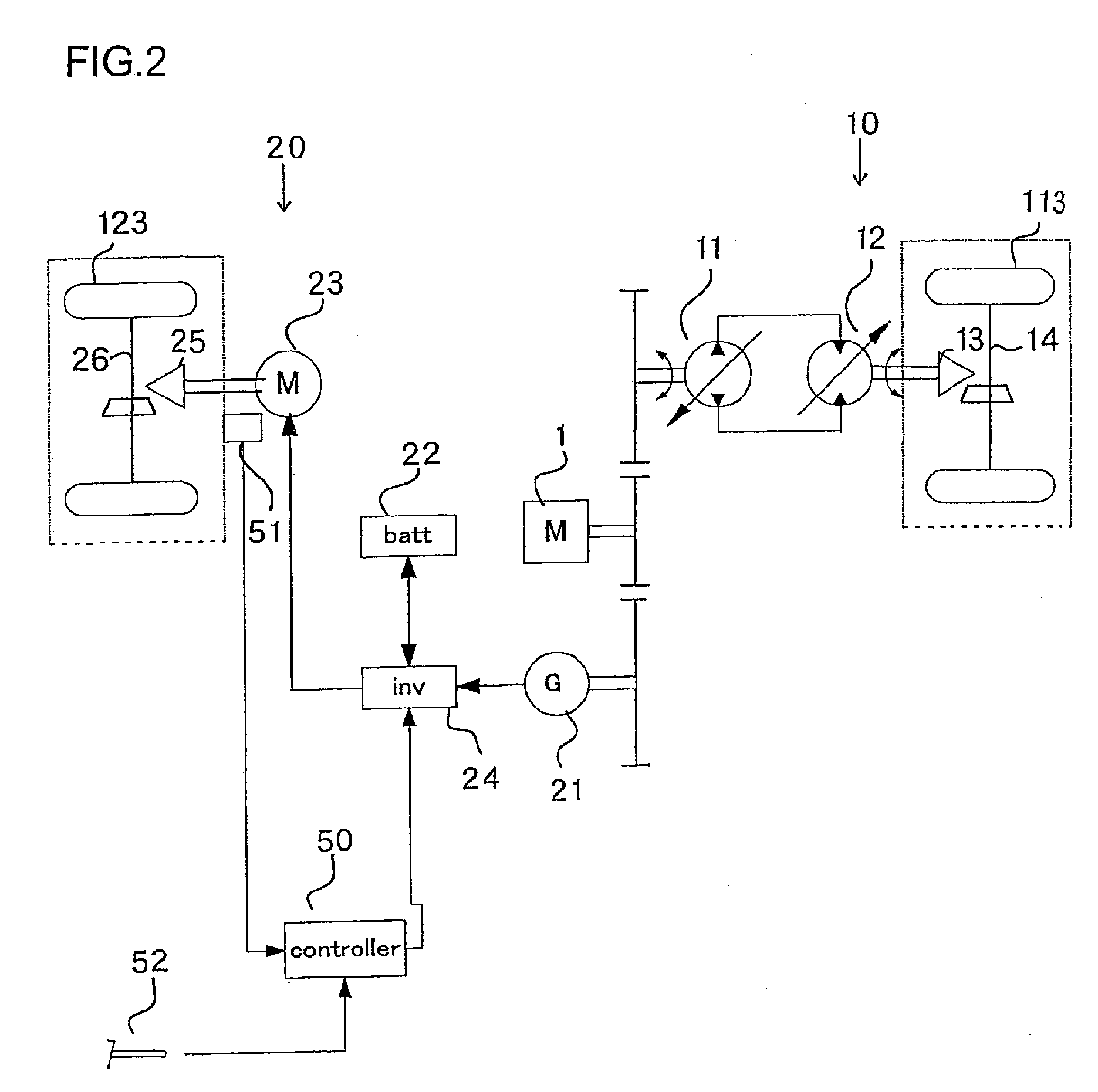
[0054]According to the second embodiment, a generator motor is provided in place of the electric motor 23 as the rear-wheel drive device 20. Kinetic energy of the vehicle is recovered during low-speed running. FIG. 8 is a schematic diagram of the travel drive system in accordance with the second embodiment. The same reference numbers are assigned to the same items in common with FIG. 2. Explanations in below is focused on the differences.

[0055]The controller 50 is connected with the vehicle speed detector 51, the operation amount detector 52 for accelerator pedal, and an operation amount detector 57 for detecting an operation amount B of a brake pedal. The controller 50 subtracts the operation amount B of the operation amount detector 57 from the operation amount A of the operation amount detector 52. The controller 50 outputs an acceleration...


PUM


Abstract

A travel drive system for a work vehicle includes: an HST drive device comprising a hydraulic pump driven by a prime mover and a hydraulic motor connected to the hydraulic pump by a closed circuit; an electric motor driven by using electric power generated by drive of the prime mover; a first drive wheel driven by the HST drive device; a second drive wheel driven by the electric motor; a vehicle speed detector that detects a vehicle speed; and a control unit that distributes output of the prime mover to the HST drive device and to the electric motor such that, as the vehicle speed detected by the vehicle speed detector increases, a proportion of a first power distributed to the HST drive device decreases and a proportion of a second power distributed to the electric motor increases.

Description

TECHNICAL FIELD[0001]The present invention relates to a travel drive system for a work vehicle such as a wheel loader and a wheel hydraulic excavator, the work vehicle, and a travel drive method.BACKGROUND ART[0002]There is a travel drive system for this sort of work vehicles known in the related art, which includes a HST travel circuit where a hydraulic pump is connected to a hydraulic motor by a closed circuit for transmitting a driving force by the hydraulic motor to wheels via a propeller shaft so as to allow the vehicle to be driven (refer to, for example, patent reference literature 1).[0003]Patent reference literature 1: Japanese Laid Open Patent Publication No. H5-306768DISCLOSURE OF THE INVENTIONProblems to Be Solved by the Invention[0004]There has been a problem which results from characteristics of an HST, that is, even though the travel drive system exerts large tractive force during low-speed running, fuel consumption deteriorates due to a gear transmission loss during ...

Claims


Application Information

Patent Timeline
Patent Type & Authority Applications(United States)
IPC IPC(8): B60W10/04F16H61/40B60W20/00B60K1/00B60K5/00B60K6/36B60K6/44B60K6/46B60K6/52B60K6/543B60K6/547B60K17/356B60L50/16B60W10/08B60W10/10E02F9/22
CPCB60K6/46Y02T10/76B60K17/04B60K17/356B60L1/003B60L2200/40B60W10/08B60W10/103B60W20/00B60W2300/17B60W2510/085B60W2520/10B60Y2200/415F16H61/475Y02T10/6217Y02T10/6265B60K6/52B60L15/20B60L15/2009B60L2210/40B60L2240/12B60L2240/421B60L2240/423B60L2250/26B60L2260/28B60L50/61Y02T10/62Y02T10/64Y02T10/72Y02T10/70B60K6/36B60W2540/10B60W2540/12B60W20/10Y02T10/7072
Inventor UDAGAWA, TSUTOMUNAKAYAMA, AKIRATOYOOKA, TSUKASASUGAYA, MAKOTO
Owner NIHON KENKI CO LTD
Why Eureka
Try Eureka