Output control system for engine with exhaust control function

a technology of output control system and engine, which is applied in the direction of machines/engines, vehicle components, process and machine control, etc., can solve the problems of deteriorating and achieve the effect of lowering engine output, ensuring sufficient engine performance and lowering fuel economy

Active Publication Date: 2005-02-10
HONDA MOTOR CO LTD
View PDF13 Cites 1 Cited by
  • Summary
  • Abstract
  • Description
  • Claims
  • Application Information

AI Technical Summary

Benefits of technology

[0009] According to the above-described system, since when the exhaust control valve is functioning abnormally, control is performed so as to lower the engine output, even when the exhaust control valve is operating such that the exhaust gas cross-sectional area becomes smaller than a set point, sufficient engine performance can be secured and the lowered fuel economy can be reduced to the minimum.

Problems solved by technology

Therefore, since when the exhaust control valve is functioning abnormally for some reason or other, the fundamental ignition timing or the fundamental injection quantity deviates from the optimum value, there is a possibility of causing problems such as deteriorated engine performance and lowered fuel economy.

Method used


Image

  • Output control system for engine with exhaust control function
  • Output control system for engine with exhaust control function
  • Output control system for engine with exhaust control function

Examples


Embodiment Construction

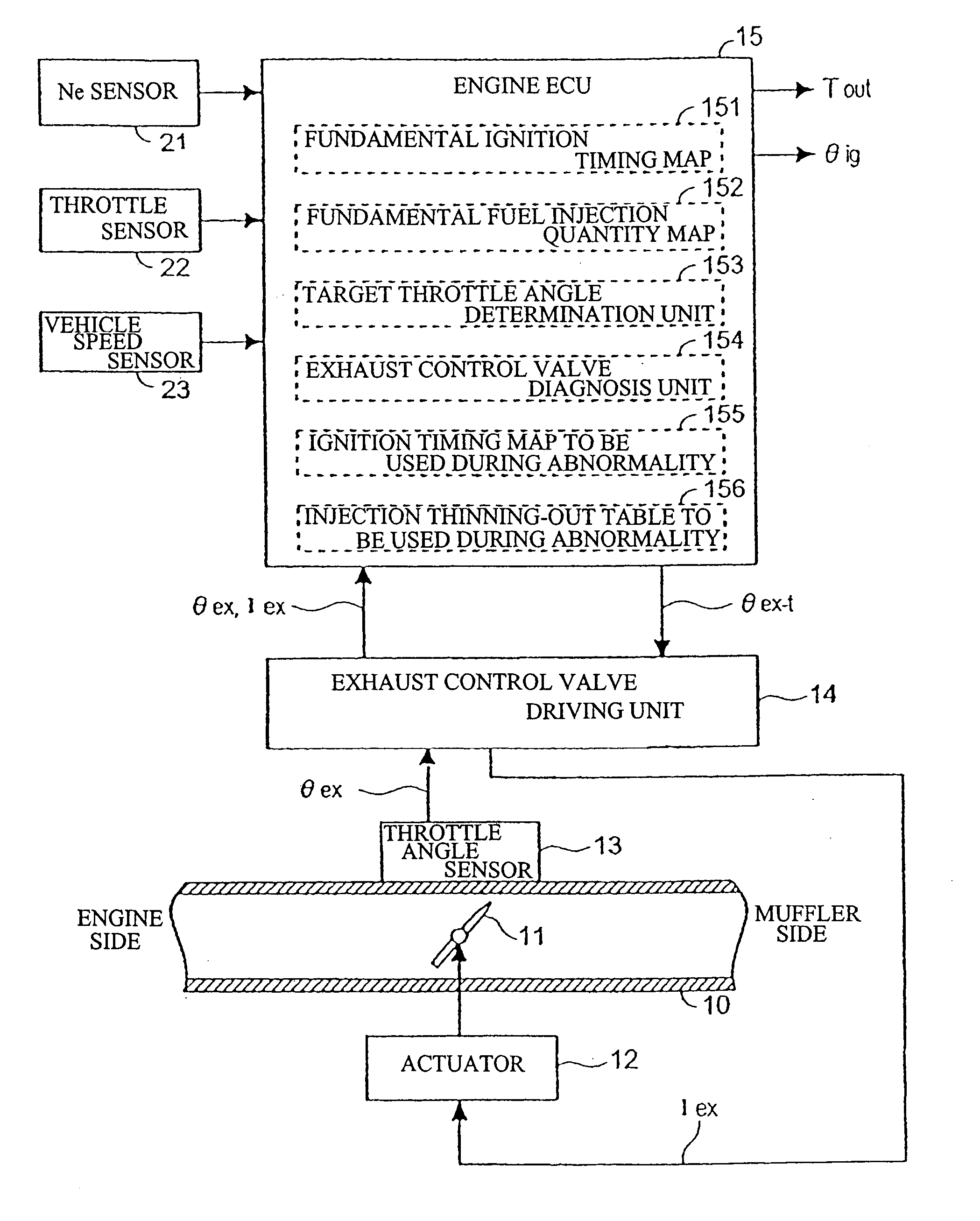
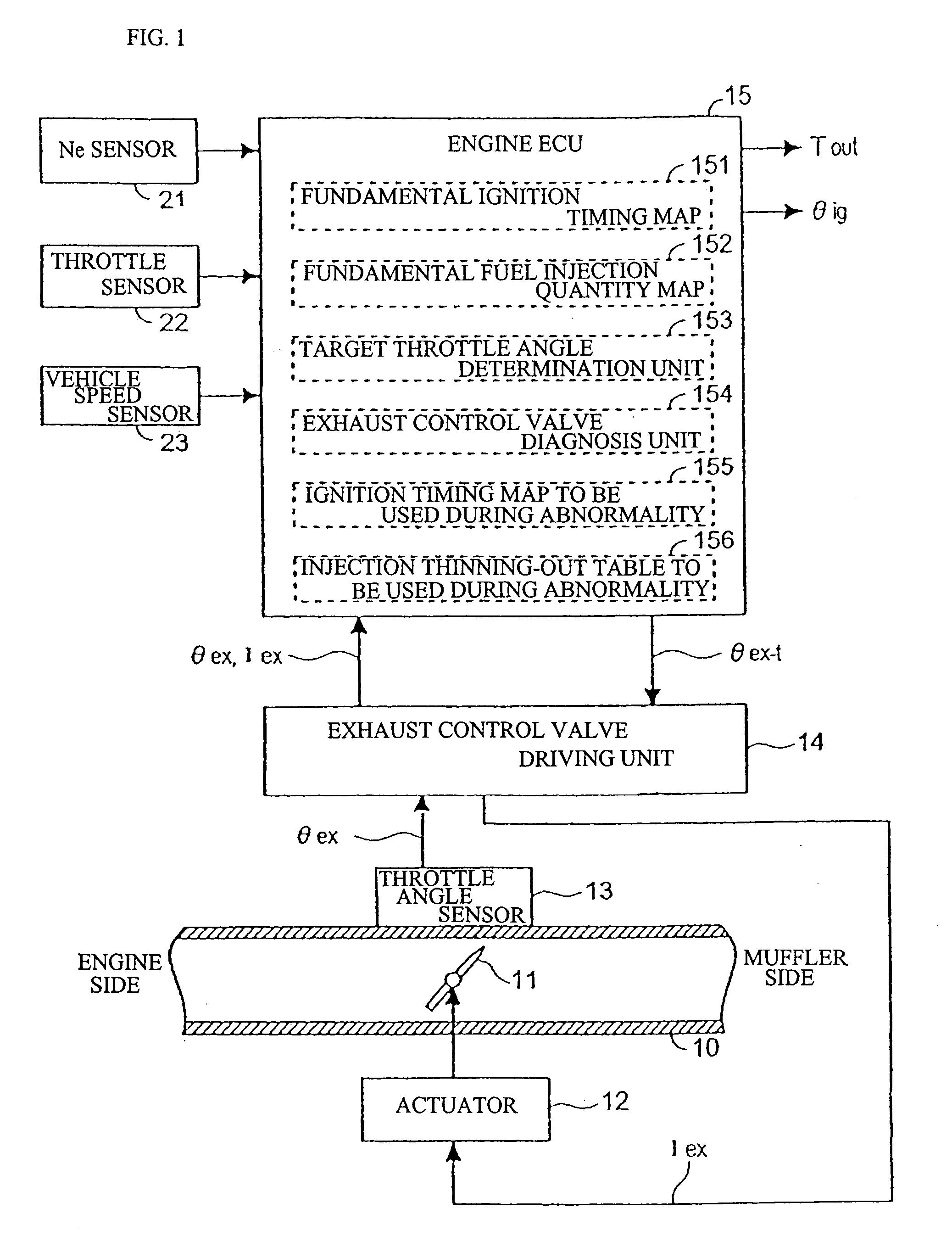
[0014] Hereinafter, with reference to the drawings, the detailed description will be made of an embodiment of the present invention. FIG. 1 is a block diagram showing structure of a principal part of an engine output control system according to the embodiment of the present invention, and within an exhaust passage 10, between an engine and a muffler, there is mounted an exhaust control valve 11. The exhaust control valve 11 variably controls the exhaust gas passage cross-sectional area by being rotated by an actuator 12 to be driven by an exhaust control valve driving unit 14. A throttle angle θex of the exhaust control valve 11 is detected by a throttle angle sensor 13, and this information is sent to the exhaust control valve driving unit 14.

[0015] An engine ECU 15 includes: a fundamental ignition timing map 151 for determining fundamental ignition timing θig (θig1) on the basis of control parameters such as engine speed Ne detected by an engine speed sensor 21, a throttle angle ...


PUM


Abstract

An engine output control system includes an engine ECU having a fundamental ignition timing map, a fundamental fuel injection quantity map, a target throttle angle determination unit for determining a target throttle angle of an exhaust control valve, an exhaust control valve diagnosis unit for diagnosing operation of the exhaust control valve, an ignition timing map to be used during an abnormality for determining fundamental ignition timing when the exhaust control valve operates abnormally, and an abnormal fuel injection thinning-out table for determining a reduced rate of fuel injection when the exhaust control valve has been diagnosed as abnormal. The exhaust control valve driving unit supplies a driving current to an actuator in such a manner that the target throttle angle notified by the engine ECU coincides with actual valve throttle angle. The system is capable of obtaining sufficient traveling performance even when an exhaust control valve has is operating abnormally.

Description

CROSS-REFERENCE TO RELATED APPLICATIONS [0001] The present invention claims priority under 35 USC 119 based on Japanese patent application No. 2003-206265, filed Aug. 6, 2003. BACKGROUND OF THE INVENTION [0002] 1. Field of the Invention [0003] The present invention relates to an output control system for an engine with an exhaust control device, and more particularly to an output control system for an engine equipped with an exhaust control function which controls an exhaust pulse by providing means such as a valve for changing an exhaust gas passage cross-sectional area midway in an engine exhaust air system. [0004] 2. Description of the Background Art [0005] In Japanese Patent Laid-Open No. 1-313621 or 2002-138828, there has been disclosed a technique for improving engine output by reducing resistance within an exhaust passage in a high speed area of an engine and utilizing a pulsation effect, or arranging an exhaust control valve for making the exhaust gas cross-sectional area va...

Claims


Application Information

Patent Timeline
Patent Type & Authority Applications(United States)
IPC IPC(8): F01N5/00F01N9/00F01N13/08F02B27/02F02B27/06F02D9/04F02D37/02F02D41/14F02D41/22F02D41/34F02D43/00F02D45/00F02P5/15
CPCF02B27/02F02B27/0263F02B27/06F02D9/04Y02T10/146F02D41/1495F02D41/221F02D2250/26F02D37/02F02B27/0294Y02T10/12F01N9/00
Inventor SUGANO, KIYOYUKISASAKI, NORIHIKOTAKAMI, NORITAKEMORIYAMA, YUICHITAMAI, HIROAKI
Owner HONDA MOTOR CO LTD
Why Eureka
Try Eureka