Process transmitter isolation assembly

Active Publication Date: 2006-07-27
ROSEMOUNT INC
View PDF13 Cites 42 Cited by
  • Summary
  • Abstract
  • Description
  • Claims
  • Application Information

AI Technical Summary

Benefits of technology

[0009] An isolation assembly for connection to a process transmitter and for mitigating high temperature effects of process fluid includes a process coupling face having an isolation diaphragm configured to contact process fluid. The isolation assembly further includes a transmitter coupli

Problems solved by technology

However, transmitters typically have a maximum operating temperature of 250-300° F. Even in cases where the transmitter can withstand the high temperature, temperature extremes can still cause errors in pressure measurements.
The use

Method used


Image

  • Process transmitter isolation assembly
  • Process transmitter isolation assembly
  • Process transmitter isolation assembly

Examples


Embodiment Construction

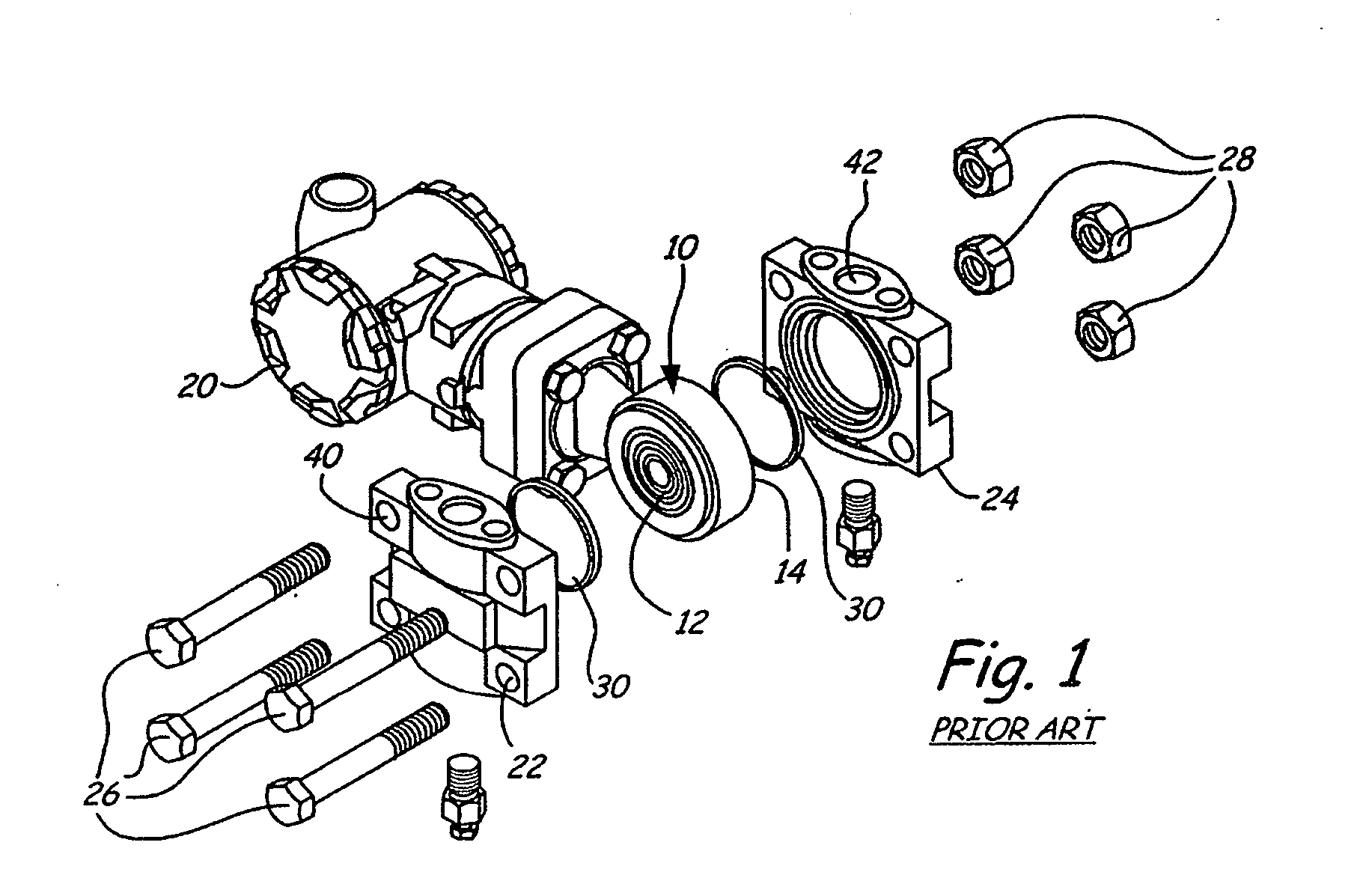
[0017]FIG. 1 is a partial exploded view of a prior art transmitter isolation assembly 10. Assembly 10 includes diaphragms 12 and 14 (not shown) and couples to a differential pressure transmitter 20. Flanges 22 and 24 bolt onto the diaphragms 12 and 14 using bolts 26 and nuts 28. O-rings 30 are provided to seal the coupling. The flanges 22 and 24 couple to process piping through process connections 40 and 42, respectively. Pressure transmitter 20 includes two isolation diaphragms (not shown) which generally lie in the same plane. Two conduits (not shown) carried within isolation assembly 10 couple each diaphragm 12 and 14 to one of the isolation diaphragms of the transmitter 20. In the prior art configuration shown in FIG. 1, the two diaphragms 12 and 14 have their faces opposed to each other and lie in different parallel planes. In contrast, the two isolation diaphragms on the pressure transmitter 20 lie in the same plane. Therefore, process couplings which are configured to couple ...


PUM


Abstract

An isolation assembly for connection to a process transmitter and for mitigating high temperature effects of a process fluid includes a process coupling face having an isolation diaphragm configured to contact process fluid. A transmitter coupling has a pressure coupling configured to couple to a pressure port of the process transmitter. A temperature isolation fluid conduit extends between the process coupling face and the transmitter coupling and carries an isolation fluid which couples a pressure applied to the isolation diaphragm to the pressure coupling to minimize high temperature effects of the process fluid on the process transmitter.

Description

[0001] The present application is a Continuation-In-Part and claims the benefit of U.S. patent application Ser. No. 10 / 876,816, filed Jun. 25, 2004, the contents of which are hereby incorporated by reference in their entirety.BACKGROUND OF THE INVENTION [0002] The present invention relates to process control transmitters of the type used in industrial process monitoring and control systems. More specifically, the present invention relates to transmitters which measure process variables in high temperature environments. [0003] Process monitoring and control systems are used to monitor and control operation of industrial processes. Industrial processes are used in manufacturing to produce various products such as refined oil, pharmaceuticals, paper, foods, etc. In large scale implementations, these processes must be monitored and controlled in order to operate within the desired parameters. [0004]“Transmitter” has become a term which is used to describe the devices which couple to the...

Claims


Application Information

Patent Timeline
IPC IPC(8): G01L19/04G01L19/00G01L19/06
CPCG01L13/025G01L19/0046G01L9/025G01L19/0681
Inventor BRODEN, DAVID A.
Owner ROSEMOUNT INC
Why Eureka
Try Eureka