
Rotary hydraulic cylinder

Inactive Publication Date: 2006-07-27
2051172 ONTARIO
View PDF9 Cites 2 Cited by
  • Summary
  • Abstract
  • Description
  • Claims
  • Application Information

AI Technical Summary

Benefits of technology

[0009] Because the vane, end discs and shaft are of unitary construction, sealing at the sides of the vane or where the vane meets the shaft, as was often required in prior art constructions, is avoided. As well, the construction of the dam, extending as it does to the

Problems solved by technology

Such actuators are faced with many technical problems.
For example, the vanes and stops are conventionally individually components mounted respectively on the shaft and on the chamber walls of the housing causing wear and distortion, as well as dislocation of these component parts and the chamber walls particularly since high fluid pressures are often involved.
As well, sealing of the chamber against leakage of fluid from one side of the vane to the other, or to the outside of the housing along the shaft, is often difficult to achieve.

Method used


Image

  • Rotary hydraulic cylinder
  • Rotary hydraulic cylinder

Examples


Embodiment Construction

[0014] In the following description, similar features in the drawings have been given similar reference numerals.

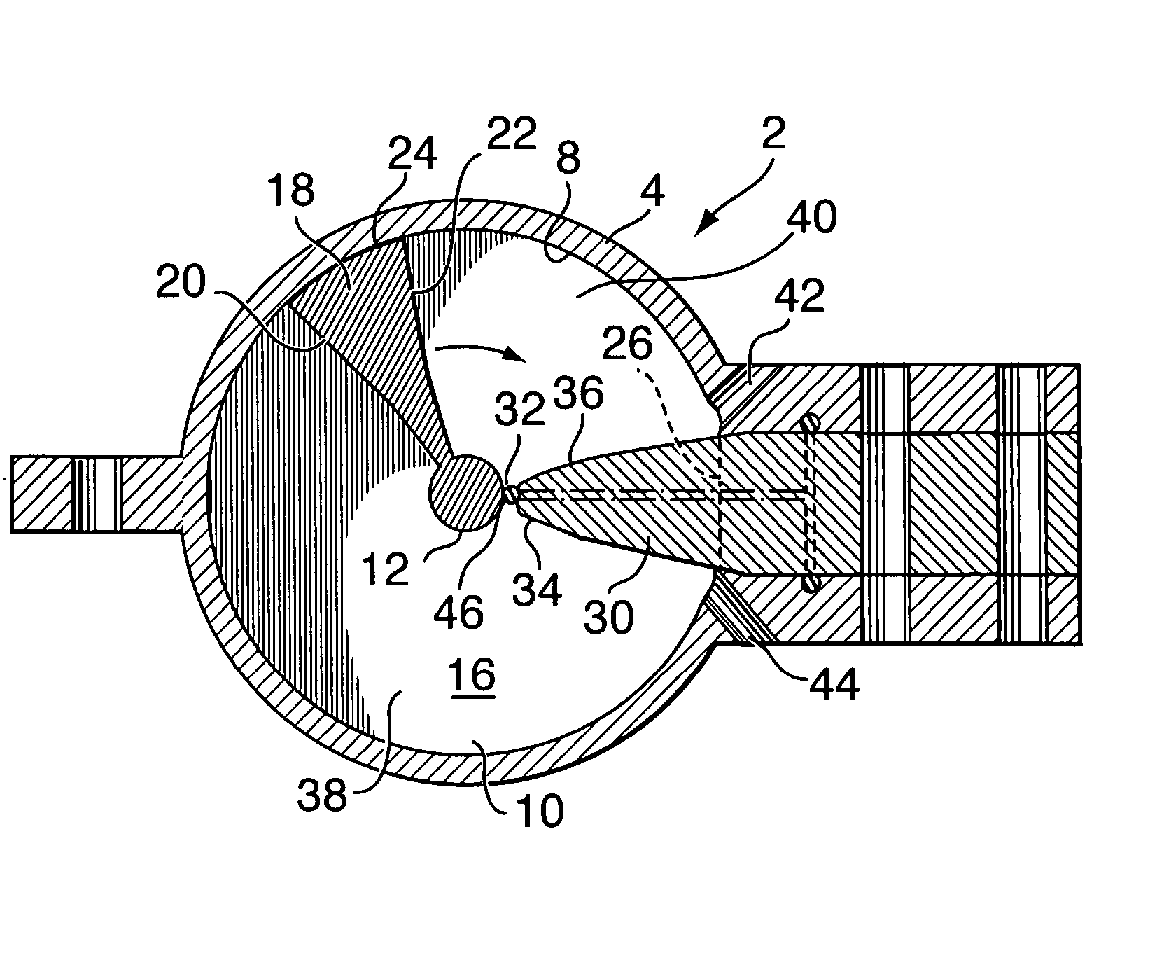
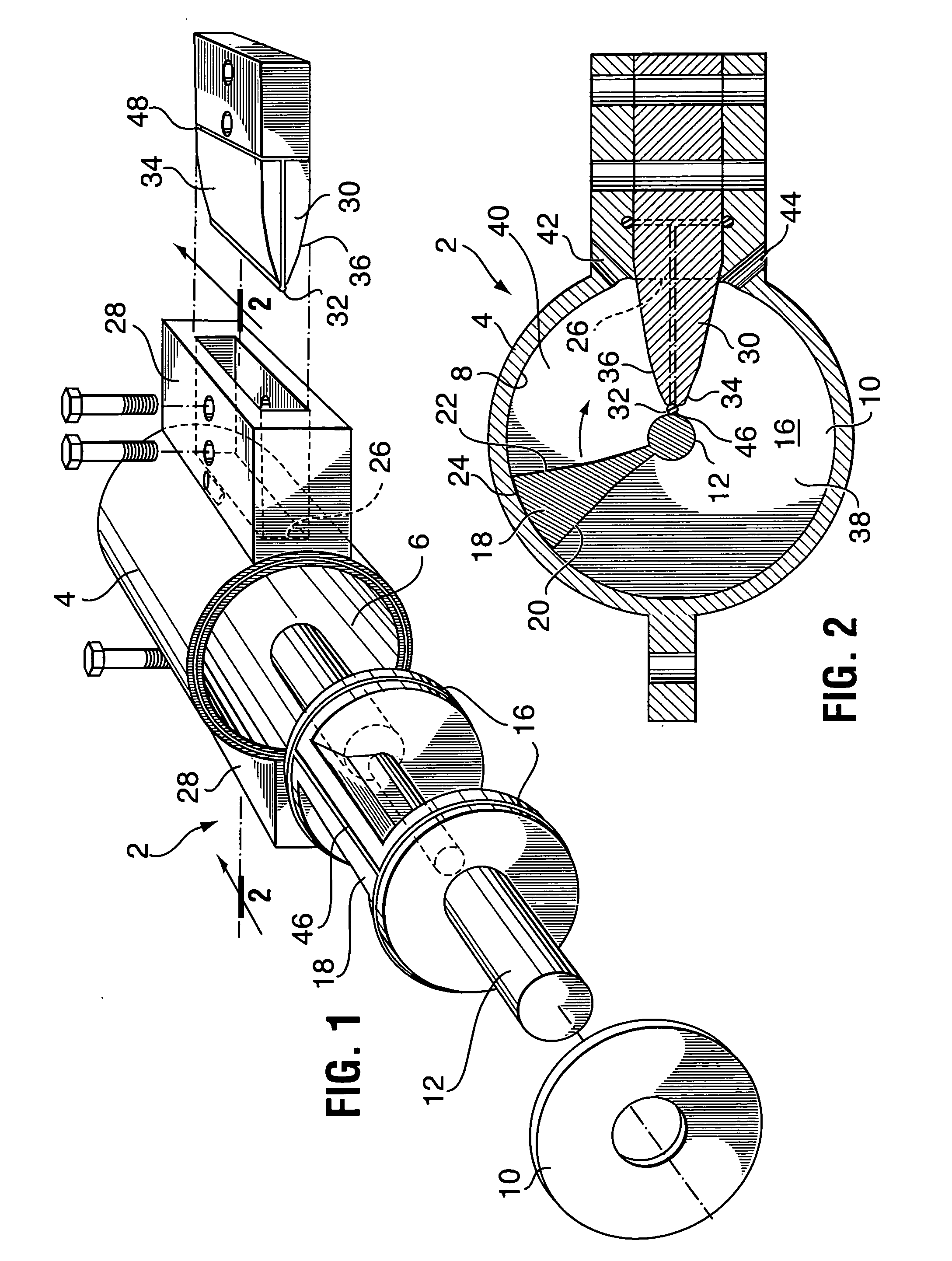
[0015] Turning to FIG. 1, there is illustrated, in exploded fashion, a rotary fluid pressure actuator 2 in accordance with the present invention. Actuator 2 comprises a housing 4 having an inner chamber 6 which has a cylindrical side wall 8 and end walls 10. End walls 10 are normal to the central axis of the cylindrical side wall.

[0016] A shaft 12 is centrally positioned within chamber 6 with respect to side wall 8, for rotation on that central axis. One end of shaft 14 extends beyond the corresponding end wall 10 for connection to, and driving, an appropriate work tool or machine component (not illustrated) beyond housing 4. Shaft 12 is supported within housing 4 by conventional bearings (not illustrated) which hold shaft 12 in alignment. End wall 10 acts as a shield to keep dirt and debris out of chamber 6. Formed as an integral unit with shaft 12 are a pair of spaced...


PUM


Abstract

A rotary fluid pressure actuator includes a housing having an inner actuator chamber with a cylindrical side wall extending between a pair of end walls. An integral vane rotor assembly, including a shaft and end discs, is positioned in the chamber and is rotationally reciprocated in response to the direction of flow of fluid to and from chamber segments of the housing. A fixed dam is secured between flanges in an elongated opening along the cylindrical side wall of the housing, the dam extending radially into the chamber from the opening to abut against the shaft between the end discs. The dam acts as a stop to limit the reciprocal motion of the vane and shaft in each direction.

Description

BACKGROUND OF THE INVENTION [0001] The present invention relates to an improved construction of rotary hydraulic or fluid pressure actuator, and more particularly to an improved construction of a vane type of such actuator. [0002] Conventional rotary fluid pressure actuators include a vane rotor assembly positioned within a sealed chamber in a housing for rotational reciprocation between positions dictated by one or more stops mounted within the housing for obstructing passage of the vane, in response to the direction of flow of fluid to and from the chamber. The vane is fixed mechanically to a shaft or the like. Hydraulic fluid pressure is exerted in sequence on the faces of the vane to rotate it and the shaft. [0003] Such devices have numerous applications, for instance in hydraulic operation of aerial work platforms (platform bracket and jib rotation), mining equipment (carousel rotation, drill positioning, rod handling, roof bolting), refuse and recycling vehicles (articulation ...

Claims


Application Information

Patent Timeline
IPC IPC(8): F01C9/00
CPCF01C9/002
Inventor PATTERSON, ALBERT W.
Owner 2051172 ONTARIO
Features
  • Generate Ideas
  • Intellectual Property
  • Life Sciences
  • Materials
  • Tech Scout
  • Unparalleled Data Quality
  • Higher Quality Content
  • 60% Fewer Hallucinations
Learn More