

Drawing-out profile for a window blind
- Summary
- Abstract
- Description
- Claims
- Application Information
AI Technical Summary
Benefits of technology
Problems solved by technology
Method used
Image

Examples
Embodiment Construction
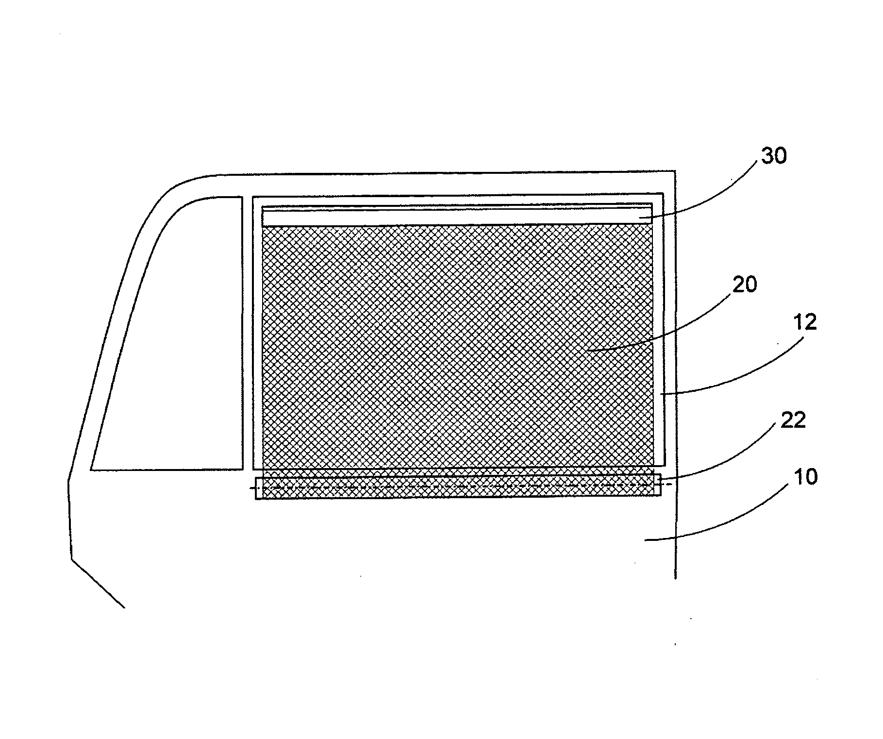
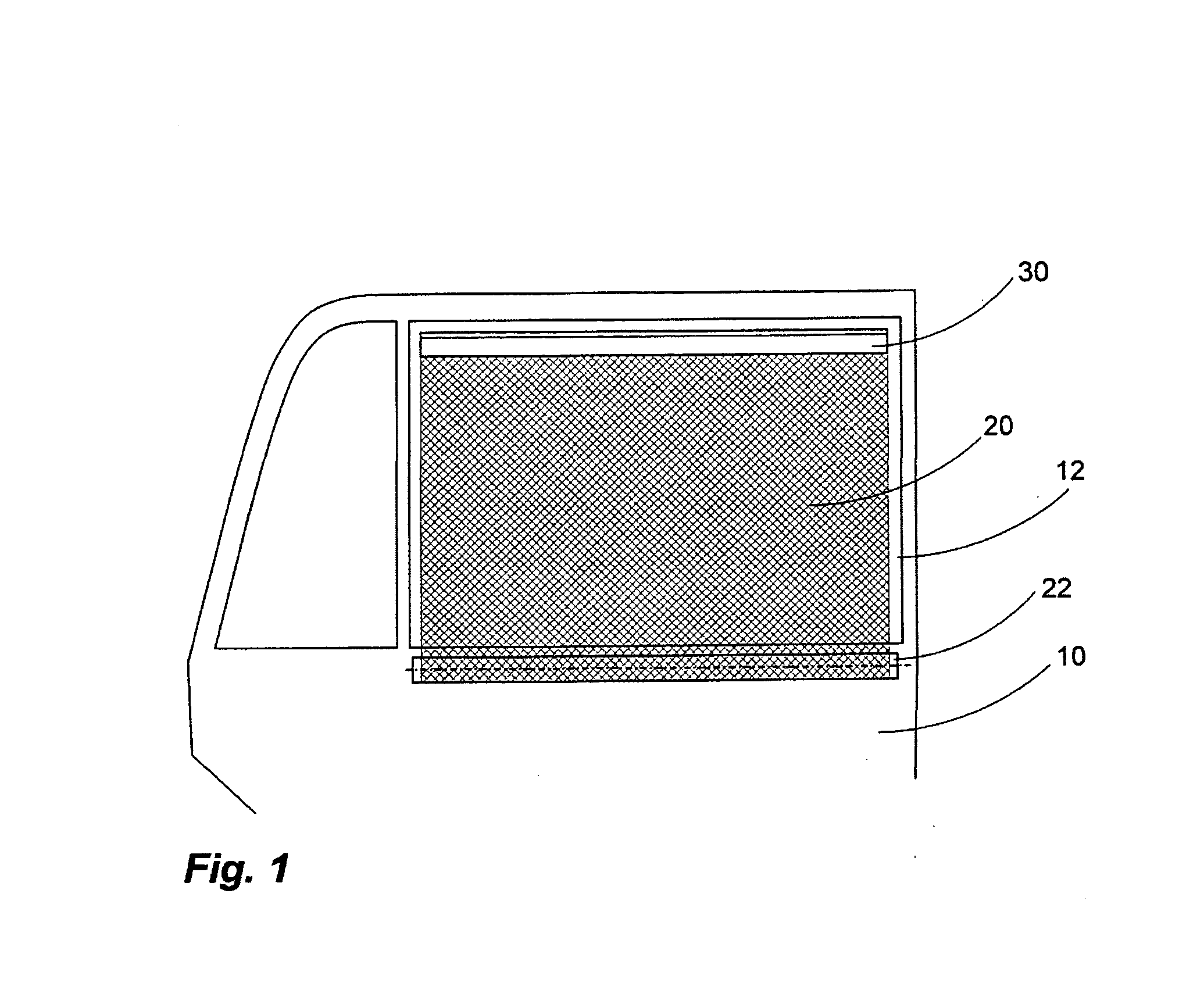
[0034]FIG. 1 shows a shading system according to the invention which is used in a vehicle door 10 of a vehicle in order to act as a sunblind for a vehicle window 12. The shading system has a flexible sheetlike structure 20 which, in a storage state (not illustrated), is rolled up on a roller blind shaft 22. In the functional state illustrated, the sheetlike structure 20 is unrolled upward from the roller blind shaft. A dimensionally stable drawing-out profile 30 is provided at the upper end of the sheetlike structure 20. Said drawing-out profile 30 gives the flexible sheetlike structure its shape and permits easy manual handling of the shading system. The drawing-out profile 30 can be designed in different ways.
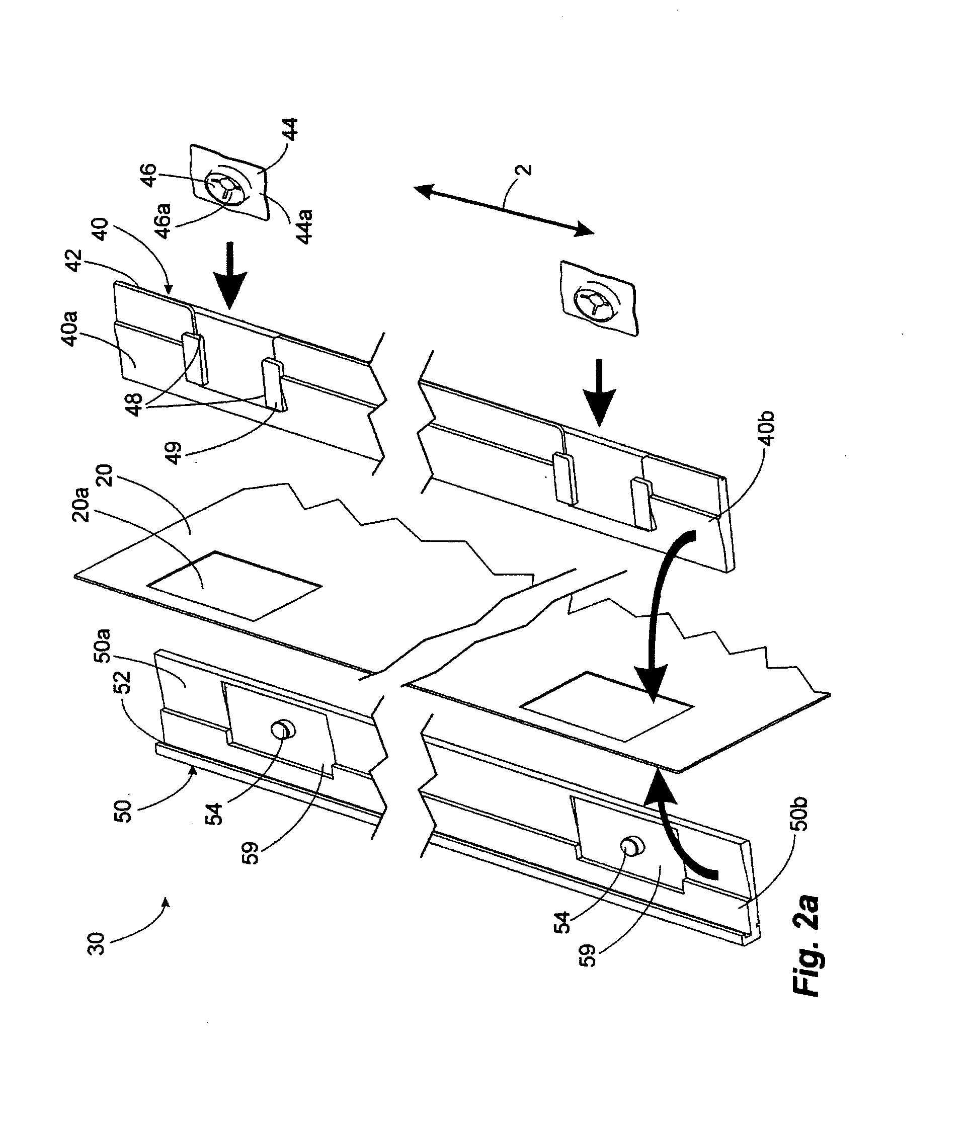
[0035]FIGS. 2 to 6 show various drawing-out profiles 30, 130, 230, 330, 430. They differ particularly in the type of connecting means by means of which the profile sections of the drawing-out profiles are connected to each other.
[0036]The drawing-out profile 30 which is illus...
PUM
 Abstract
Description
Claims
Application Information