Pusher apparatus for merchandise

a technology for pushing apparatuses and merchandise, which is applied in the field of pushing apparatuses, can solve the problems of spilt merchandise, the speed of the pushing machine is also a problem, and the known pusher apparatus suffers various problems, so as to avoid the problem of potential injury and spilt merchandis

Inactive Publication Date: 2006-07-27
GAMBLE NIGEL FRANCIS
View PDF15 Cites 207 Cited by
  • Summary
  • Abstract
  • Description
  • Claims
  • Application Information

AI Technical Summary

Benefits of technology

[0011] In an alternative preferred embodiment, a first end of the coil spring is attached to a front end of the track and the second end of the spring is attached to the pusher, whereby the coiling of the spring draws the pusher along the track. In this embodiment the pusher is started from a fixed point at the end of the track and its forward movement ends when it returns to the fixed point. That is not necessarily when the spring is in a fully relaxed condition, which has the advantage that the spring may still provide a useful driving force even near the end of the track. The same embodiment may further comprise a second axle rotatably mounted on the pusher, wherein the spring is coiled about the second axle and the second end of the spring is attached to the second axle. By using separate axles for mounting the spring and the cogs, each axle can be designed optimally for its own function and it is not necessary to ensure that the number of turns on the spring matches the number of turns of the cogs.
[0015] It is strongly preferred that the pusher apparatus comprises a rotary damper mounted on the pusher for regulating the rate of coiling or uncoiling of the spring. The damper allows the use of a spring strong enough to move the largest loads expected when the stack is full but prevents the pusher from moving too fast when only a light load is present. Therefore the problems of potential injury and of spilt merchandise are avoided. The damping effect of the rotary damper may be adjustable so that a single design of pusher apparatus can accommodate merchandise of widely differing weights. Other kinds of damper such as a linear damper arranged along the track could also be used.

Problems solved by technology

The known pusher apparatus suffers various problems.
In the prior art, the speed of the pusher has also been a problem.
When the same spring is acting on only a few items in the stack, it can accelerate them violently and push them too rapidly along the track There is a risk of injury to the fingers of a person who is loading the apparatus.
There is also a risk that the rapidly moving items will be ejected from the front of the stack, causing them to fall and be damaged.
To avoid the latter risk, the height of the retaining lip at the front of the track must be increased, which makes the items less visible and less accessible and requires a greater space above the shelf so that items can be lifted over the lip.
Known pushers have been found not to work well in cold environments such as chiller or freezer cabinets.
There is a problem with the build up of frost along the track, which impedes the sliding movement of the pusher unit.
There is also a problem of ice adhering the pusher unit to the track.

Method used


Image

  • Pusher apparatus for merchandise
  • Pusher apparatus for merchandise
  • Pusher apparatus for merchandise

Examples


Embodiment Construction

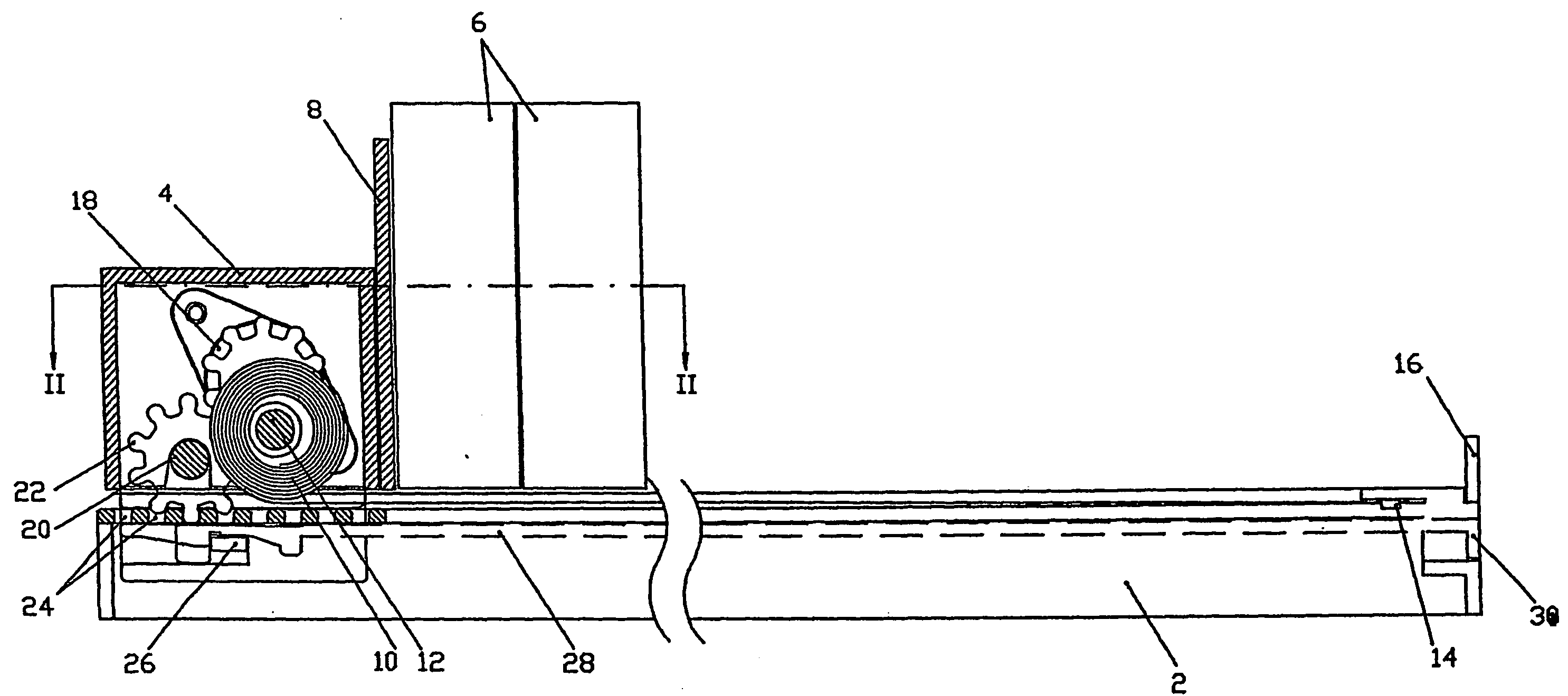
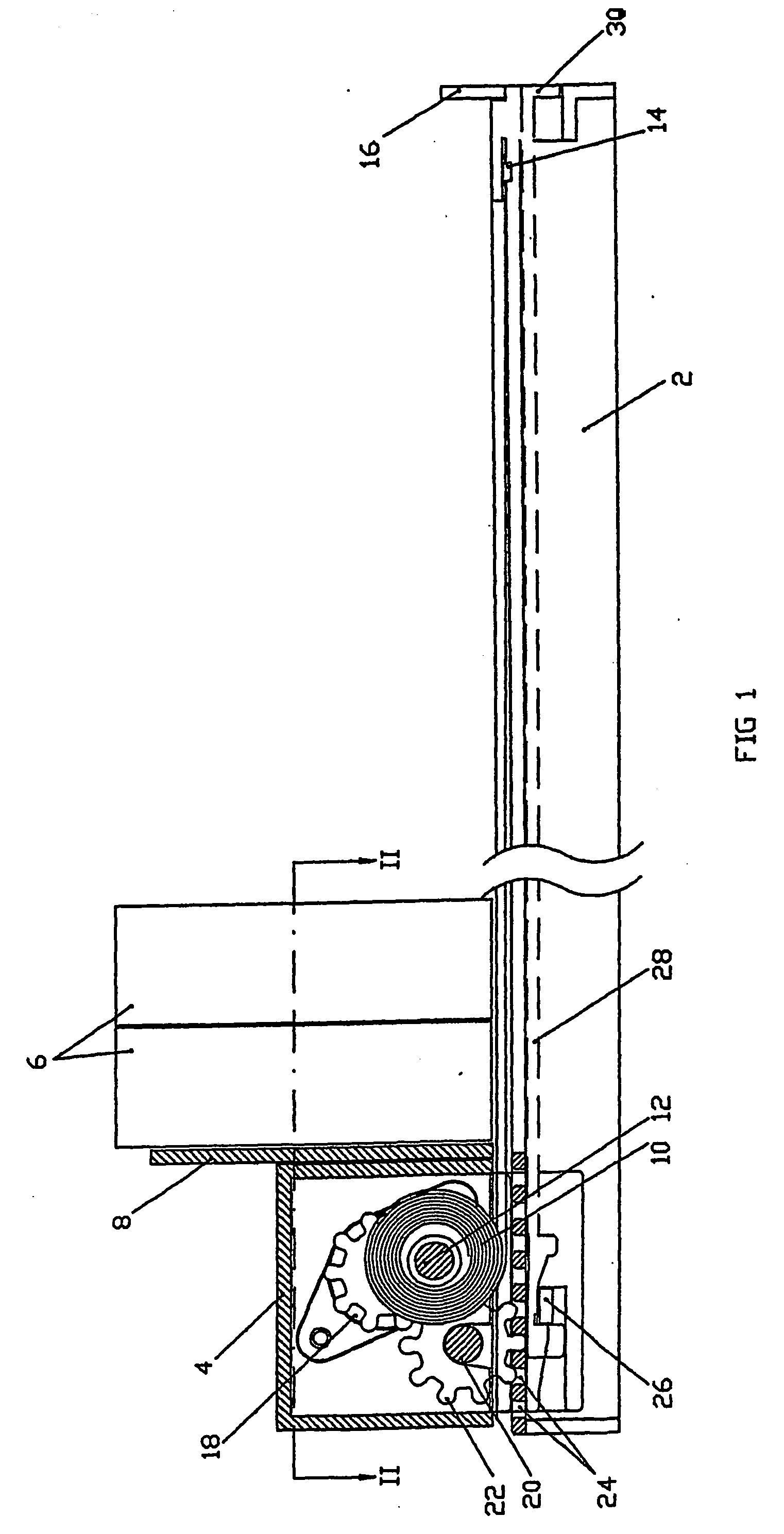
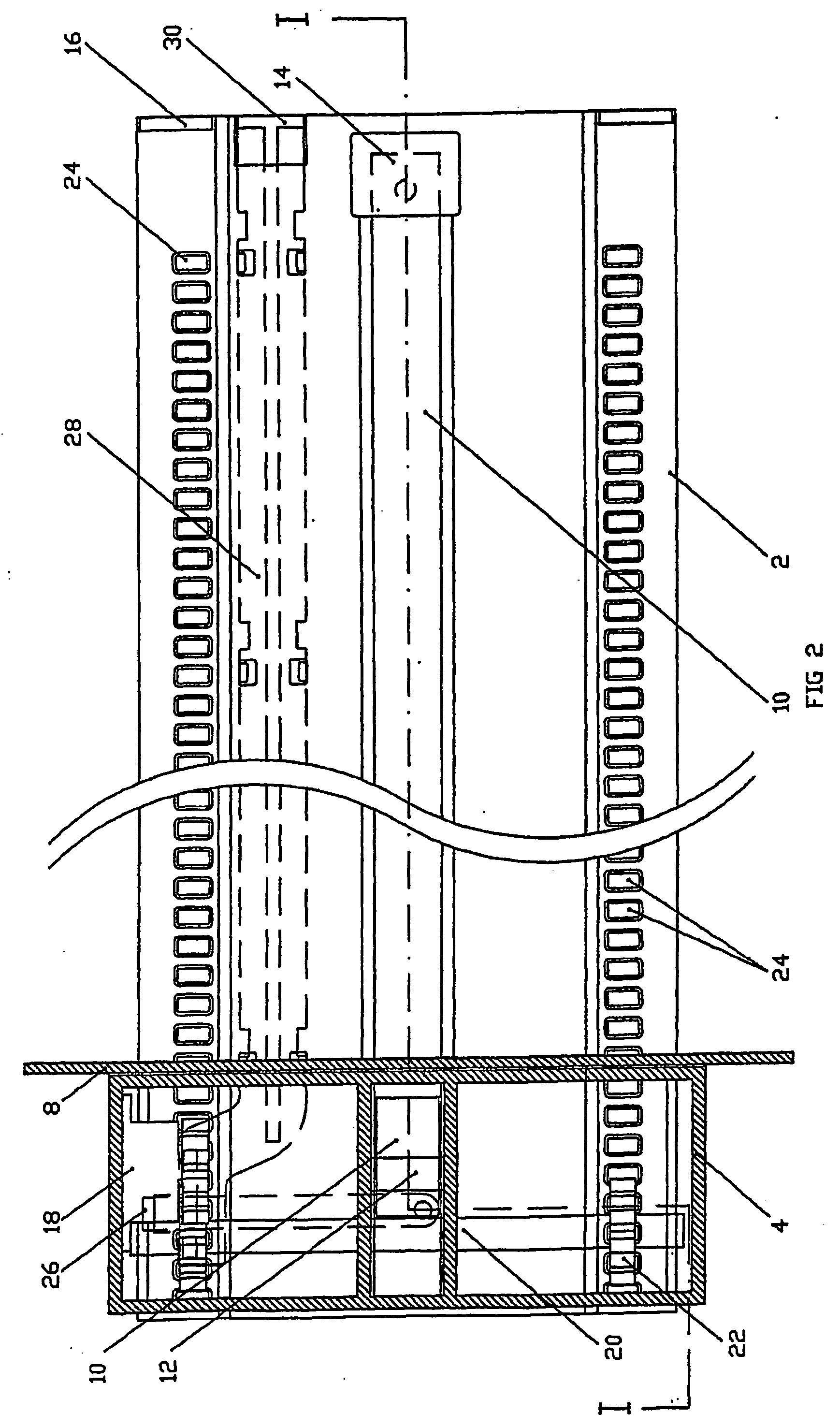
[0022] The pusher apparatus shown in FIGS. 1 to 4 comprises an elongate track 2, which in use rests on or is integral with a shelf (not shown) for displaying merchandise. A pusher unit 4 is mounted on the track 2 so as to be capable of sliding along the track 2. Merchandise 6 for display is stacked along the track 2 and is engaged by a pusher plate 8 of the pusher unit 4.

[0023] A coil spring 10 is coiled about a spring axle 12 that is rotatably mounted in the pusher unit 4, one end of the spring being attached to a ring (not shown) freely rotatable on the spring axle 12. The other end of the spring is attached at 14 to the track 2, near to the front end of the track 2. As the pusher unit 4 is drawn back along the track to the position shown in FIG. 1, the spring 10 uncoils and lies flat along the track 2. The natural tendency of the spring 10 to coil up again draws the pusher unit 4 forwards along the track 2, pushing the items of merchandise 6 on the track ahead of it, until the f...


PUM


Abstract

A pusher apparatus comprises a track, a pusher mounted on the track for movement along the track; a spring mounted on the pusher for urging the pusher along the track; an axle rotatably mounted on the pusher; and at least one wheel fixed to the axle for positively engaging the track. In one aspect of the invention, two of the said wheels are fixed to the axle to avoid canting of the pusher as it moves along the track. In another aspect of the invention, the spring is a coil spring contained within the pusher unit for driving rotation of the axle. Preferably, a rotary damper regulates the operation of the coil spring.

Description

TECHNICAL FIELD [0001] The invention relates to the field of pusher apparatus, i.e. apparatus for pushing a stack of items along a track. The main application for pusher apparatus is in merchandising of items for sale, whereby the front item of the stack of merchandise is always pushed to the front of the shelf. Pusher apparatus according to the invention may also operate vertically or at other angles and words such as “front”, “forwards” and “backwards” in this specification are not intended to limit its scope to horizontal operation. Pusher apparatus may clearly also be used in other situations where items are to be dispensed to a user, not necessarily for sale. BACKGROUND [0002] It is known to use a pusher apparatus for automatically pushing items of merchandise to the front of a shelf, where they are more readily visible and accessible to a potential purchaser. This may particularly promote one type of merchandise, which is stacked on a pusher apparatus and therefore prominent a...

Claims


Application Information

Patent Timeline
Patent Type & Authority Applications(United States)
IPC IPC(8): B65H1/14A47F1/12
CPCA47F1/126
Inventor GAMBLE, NIGEL FRANCIS
Owner GAMBLE NIGEL FRANCIS
Why Eureka
Try Eureka