Refillable grout dispenser with guide

a dispenser and grout technology, applied in the field of dispensers, can solve the problems of compound back up into the tip and blockage of the opening, gap in the sealing compound, waste of repeated disposal of empty tubes,

Inactive Publication Date: 2006-07-27
PEAY JAMES M
View PDF34 Cites 25 Cited by
  • Summary
  • Abstract
  • Description
  • Claims
  • Application Information

AI Technical Summary

Benefits of technology

[0009] The refillable grout dispenser with guide has a reversible dispensing tip that fits into either end of a caulking tube. The dispenser is operated by standard caulking guns. A plunger disc is pushed through the tube by the caulking gun plunger, forcing the grout out the dispensing tip. The plunger disc has an outer diameter slightly less than the inner diameter of the caulking ...

Problems solved by technology

Repeatedly disposing of these empty tubes is wasteful and harmful to the environment over time.
Any gaps in the application of the compound may create a number of problems, such as allowing heat and moisture to pass through barriers, allowing pests, such as insects and rodents, to ...

Method used


Image

  • Refillable grout dispenser with guide
  • Refillable grout dispenser with guide
  • Refillable grout dispenser with guide

Examples


first embodiment

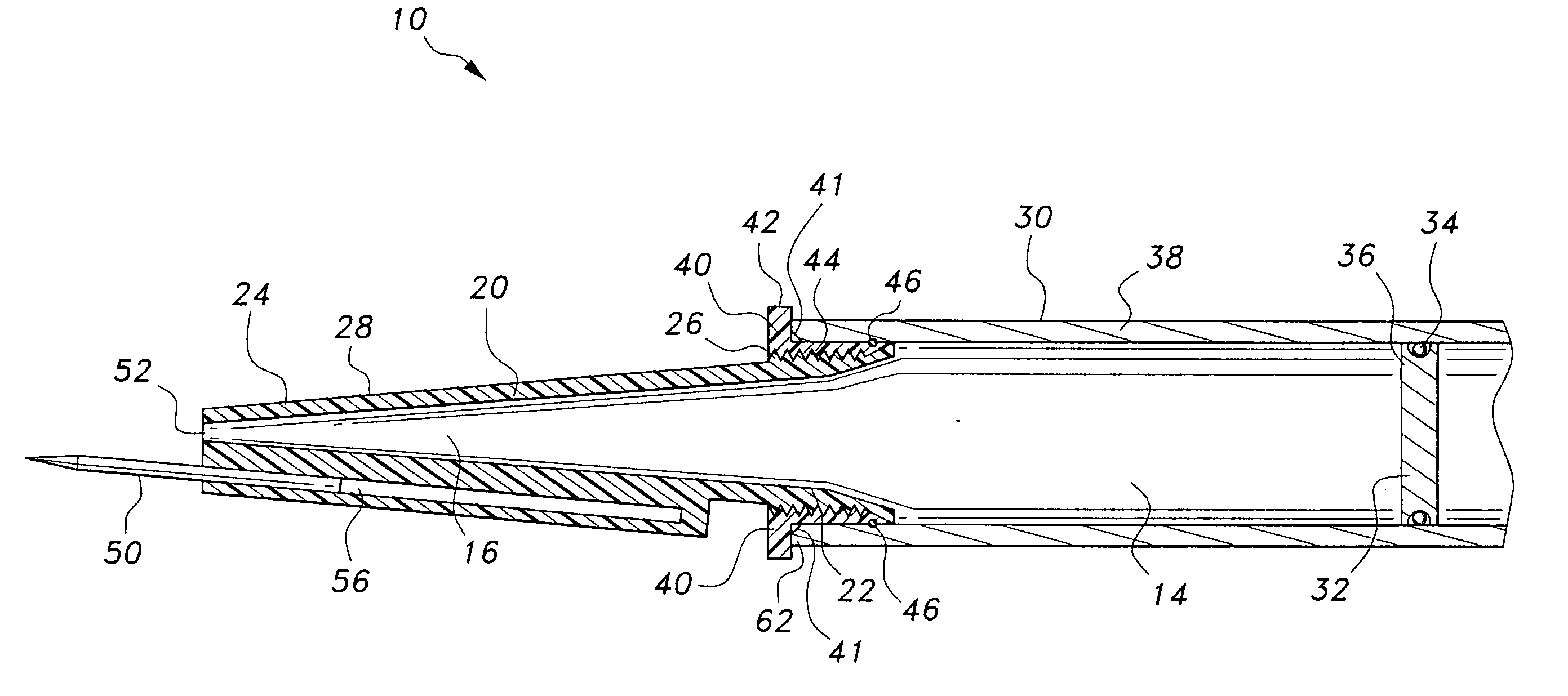
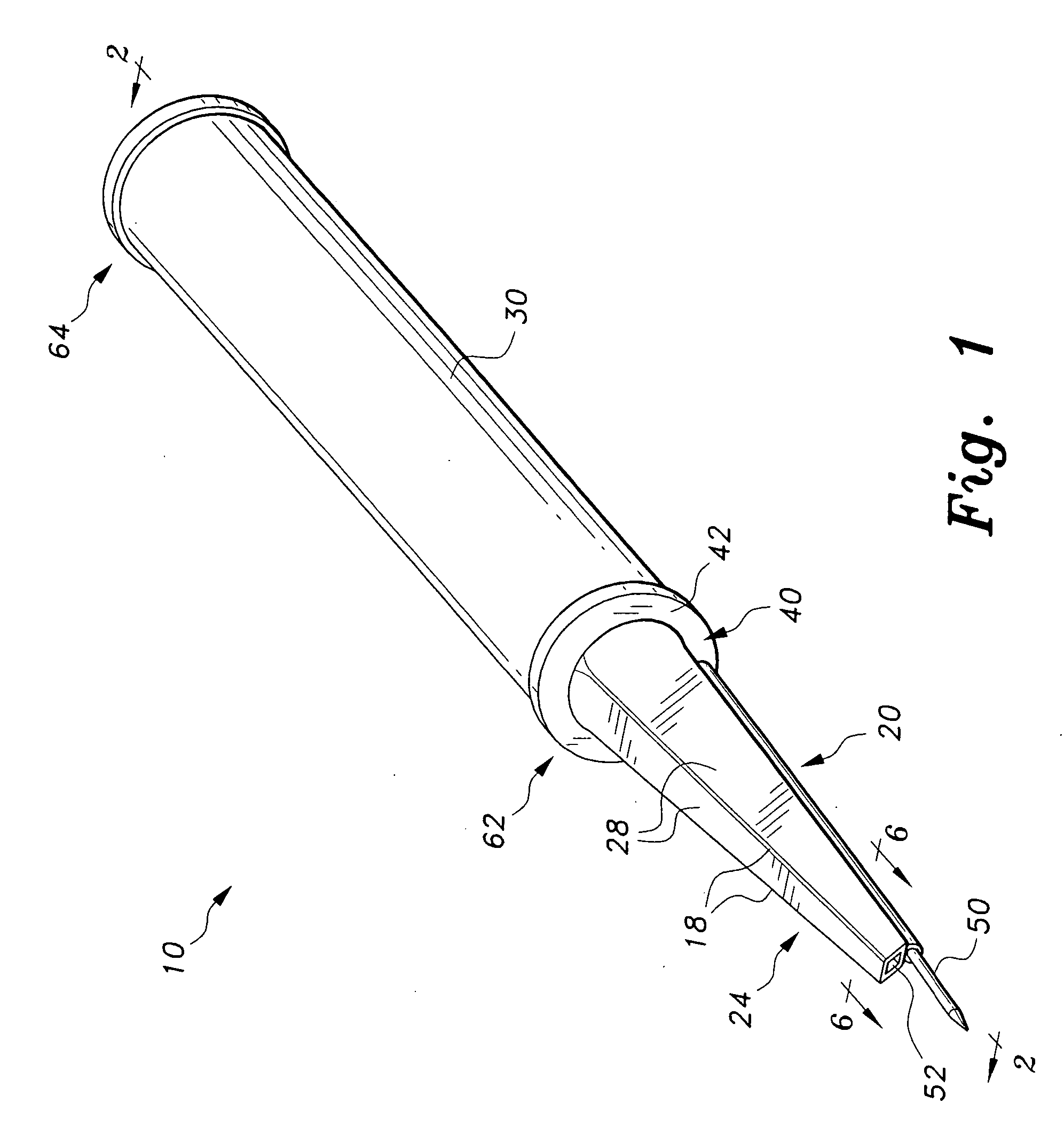
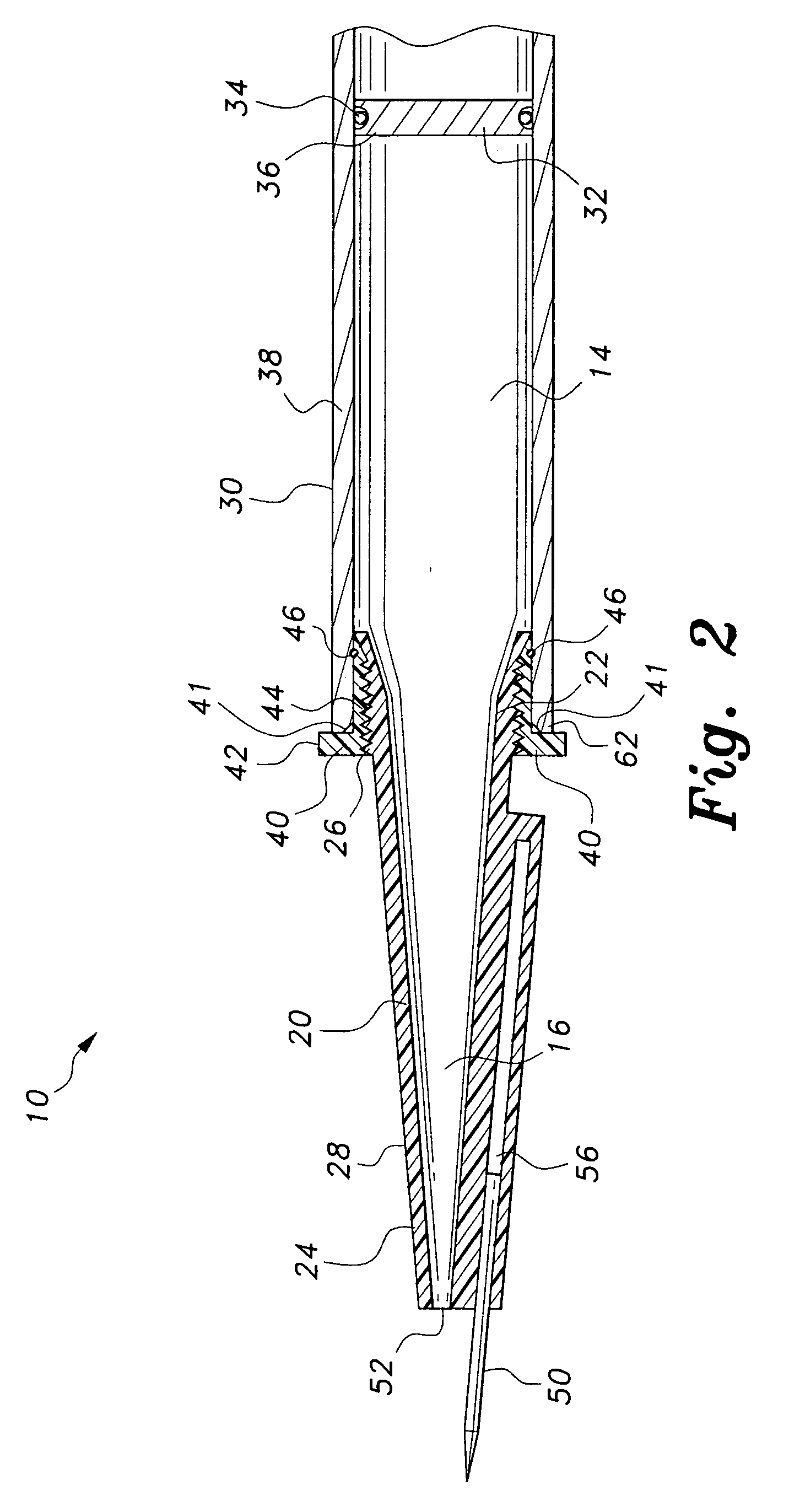
[0025] Referring to FIGS. 1 and 2, in a first embodiment, jam ring 40 slides into the end 62 of the tube 30 and holds the dispensing tip 20 to the tube 30 using a compression fit. To aid in the insertion of jam ring 40 into the end 62 of tube 30, the inside edge 41 of the tube end 62 may be beveled. The jam ring 40 has a flange 42 extending radially from one end of the ring 40. The flange 42 acts as a stop to prevent the jam ring 40 from being pushed completely into the tube 30, holding the jam ring 40 at the end 62 of the tube 30. The jam ring 40 has screw-threading 44 along its inner diameter in order to allow the dispensing tip 20 to be attached to the jam ring 40. The jam ring 40 is expandable, so that when the dispensing tip 20 is screwed into the jam ring 40, the jam ring 40 is pressed outward, forming the compression fit against the inside wall 38 of the tube 30, thereby holding the dispensing tip 20 in the tube 30.

[0026] An O-ring 46 or gasket may be secured around the outer...

second embodiment

[0027] Referring to FIGS. 3 and 4, in a second embodiment, receiving end 43 of dispensing tip 20 includes a locking pin 45 that extends radially outward from the outer side of the receiving end 43. The dispensing tip 20 has a flange 49 extending radially therefrom adjacent to the receiving end 43. The end 62 of tube 30 has an L-shaped slot 47 defined therein, the slot 47 having an axial leg 51 that extends inward from the edge of tube end 62 and a transverse leg 53 substantially perpendicular to the end of axial leg 51. To assemble the refillable grout dispenser of this embodiment, receiving end 43 of dispensing tip 20 is inserted into, and forms a compression fit with, the end 62 of tube 30, with locking pin 45 engaging and sliding down the axial leg 51 of L-shaped slot 47. To aid in the insertion of the receiving end 43 into the end 62 of tube 30, the inside edge 41 of the tube end 62 may be beveled.

[0028] Once the receiving end 43 of dispensing tip 20 is fully inserted into tube ...


PUM


Abstract

The refillable grout dispenser with guide has a reversible dispensing tip that fits into either end of the tube. The dispenser is operated by standard caulking guns. A plunger disc is pushed through the tube by the caulking gun plunger, forcing the grout out the dispensing tip. The dispensing tip may be removed from one end of the tube, and may be re-installed on the other end of the tube so that the tube may be refilled with grout and used again. The tip has a guide pin extending from near its opening. The guide pin helps keep the dispensing tip raised above the surface the grout is being applied to, and also helps the user move the dispenser along the desired path. The outer surfaces of the dispensing tip may be flat to help the user grip the tip when removing or installing it.

Description

CROSS-REFERENCE TO RELATED APPLICATION [0001] This application claims the benefit of U.S. Provisional Patent Application Ser. No. 60 / 646,529, filed Jan. 25, 2005.BACKGROUND OF THE INVENTION [0002] 1. Field of the Invention [0003] The present invention relates to dispensers. More specifically, the invention relates to dispensers used in dispensing grout, caulk, or other similar materials. [0004] 2. Description of the Related Art [0005] Caulk, grout and other sealing compounds used in building construction are often sold in tubes. The tubes are designed to fit into dispensing mechanisms known as caulking guns. The tubes usually have an opening at their front end through which the compound is dispensed when a plunger at the back of the caulking gun is pushed through the tube and toward the front opening. When all of the sealing compound is pushed out of the tube, the empty tube is removed from the caulking gun and replaced with a new, full tube. Repeatedly disposing of these empty tube...

Claims


Application Information

Patent Timeline
IPC IPC(8): A63C19/08B65D88/54
CPCB05C17/00509B05C17/00513B05C17/00516B05C17/00589B65D83/0005B05C17/00596
Inventor PEAY, JAMES M.
Owner PEAY JAMES M
Why Eureka
Try Eureka