Self-compensating drip irrigation emitter, comprising a unidirectional flow device

a drip irrigation and self-compensation technology, applied in the field of self-compensation drip irrigation emitters, comprising a unidirectional flow device, can solve the problems of earth entering and making it unusabl

Inactive Publication Date: 2006-07-27
IRRIMON
View PDF6 Cites 58 Cited by
  • Summary
  • Abstract
  • Description
  • Claims
  • Application Information

AI Technical Summary

Problems solved by technology

This system, however, also presents a problem: the obstruction of the drippers, when the direction of flow of the water is reversed due to a change in pre...

Method used


Image

  • Self-compensating drip irrigation emitter, comprising a unidirectional flow device
  • Self-compensating drip irrigation emitter, comprising a unidirectional flow device
  • Self-compensating drip irrigation emitter, comprising a unidirectional flow device

Examples


Embodiment Construction

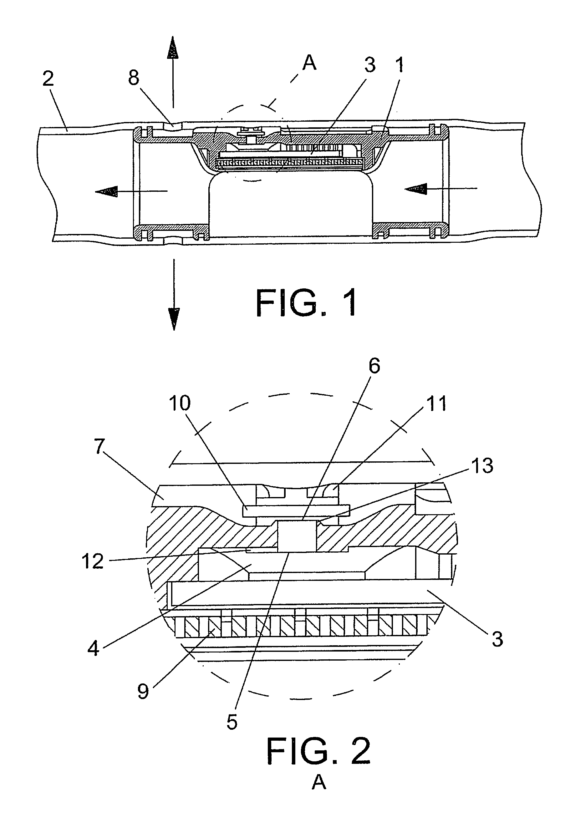
[0007] The purpose of the invention which represents the object of this Patent consists of contributing improvements to the means of sealing the water emitter outlet, when negative pressures are created in the pipe in which it is housed.

[0008] To this end, the nature, form and arrangement of this known sealing means has been modified, improving its function features and transforming the emitter into one that is essentially different

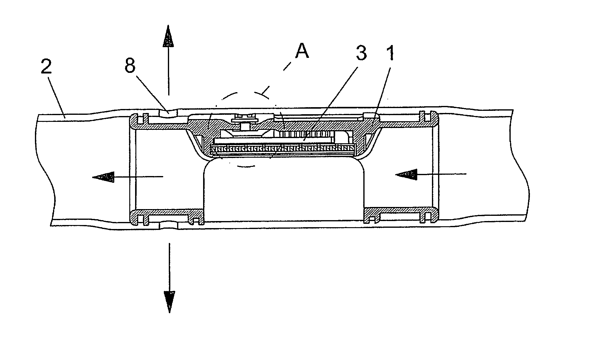
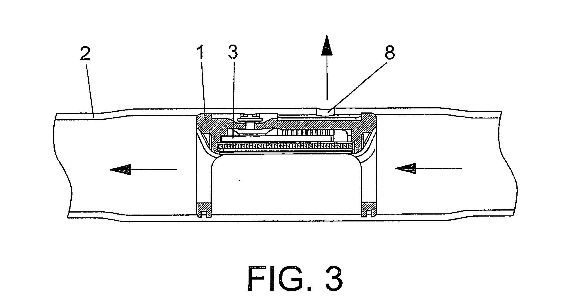
[0009] In fact, the essence of the invention consists of the replacement of the known anti-suction ball valve with a circular membrane of an elastomer material which is deformed as the pressure builds up in the pipe until it lifts off its seat at the time of the start of irrigation, so that the water runs out freely.

[0010] When, as a result of irregularities in the ground being irrigated or negative pressures in the pipes, i.e., when the external pressure is higher than the internal, a reverse flow is generated in conventional emitters not provided wit...


PUM


Abstract

The object of this Patent is “Self-compensating drip emitter, with a one-way flow device”, which has a use as explained in the actual disclosure of the invention.
Its structure comprises a conventional dripper (1) inserted or installed in a pipe (2), with a self-compensating membrane (3) that regulates the flow in the chamber (4) for its discharge via the orifice (8), being provided with a filter cover (9) which supports the membrane (3).
Its essentiality lies in the use of a circular membrane (10) as a sealing diaphragm, which rests on a watertight fillet when the internal pressure in the pipe (2) is lower than the external pressure, while it rests on another stop (11) composed of retaining tabs when the pressures are inverted.

Description

OBJECT OF THE INVENTION [0001] The object to which the invention refers that is protected in this Patent consists of a “Self-compensating drip emitter, with a one-way flow device”, i.e. inside which the direction of the water circulation cannot be reversed because it would become a suction system instead of an emitter. BACKGROUND OF THE INVENTION [0002] Self-compensating drippers are already known, in which the outlet section varies in inverse proportion to the variations in pressure, with the result that the irrigation flow is kept practically constant. This is achieved by means of the use of a peripheral elastic membrane which withstands the pressure of the water in the pipe in which the dripper is inserted on its outer face, while a small pressure is exerted on its inner face, adjoining the outlet orifice, by the flow of the liquid along a labyrinth, which gives rise to a loss of head. [0003] With this arrangement, if the pressure in the pipe is relatively high at the point where...

Claims


Application Information

Patent Timeline
IPC IPC(8): B05B15/00A01G25/02
CPCA01G25/023Y02A40/22
Inventor MARI, JUAN DUART
Owner IRRIMON
Why Eureka
Try Eureka