Acoustic transducer and underwater sounding apparatus

a transducer and sounding technology, applied in the direction of mechanical vibration separation, instruments, measurement devices, etc., can solve the problem of not being able to arrange hexagons on the surface of the cylindrical portion, and achieve the effect of reducing the deviation of directivity and suppressing the grating lob

Active Publication Date: 2006-07-27
FURUNO ELECTRIC CO LTD
View PDF9 Cites 25 Cited by
  • Summary
  • Abstract
  • Description
  • Claims
  • Application Information

AI Technical Summary

Benefits of technology

[0011] Accordingly, it is an object of the invention to provide a transducer having a cylindrical portion and a hemispherical portion, the transducer including a plurality of transducer elements arranged with special consideration to suppress grating lobes occurring in a vertical direction. It is another object of the inventi

Problems solved by technology

Since the transducer elements are arranged on a curved side surface of the cylindrical portion, it is

Method used


Image

  • Acoustic transducer and underwater sounding apparatus
  • Acoustic transducer and underwater sounding apparatus
  • Acoustic transducer and underwater sounding apparatus

Examples


Embodiment Construction

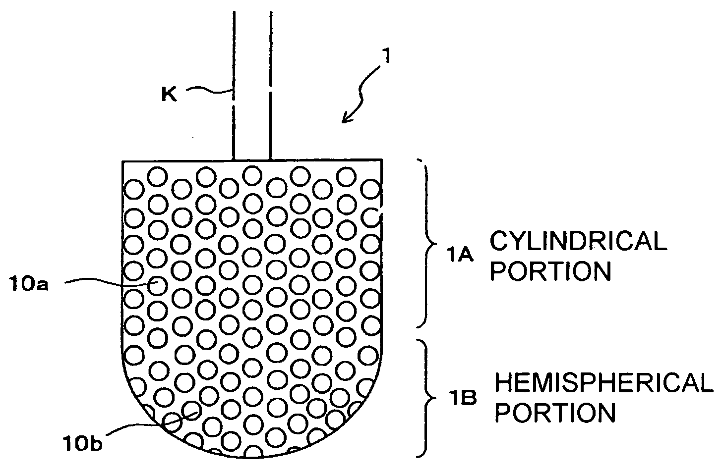
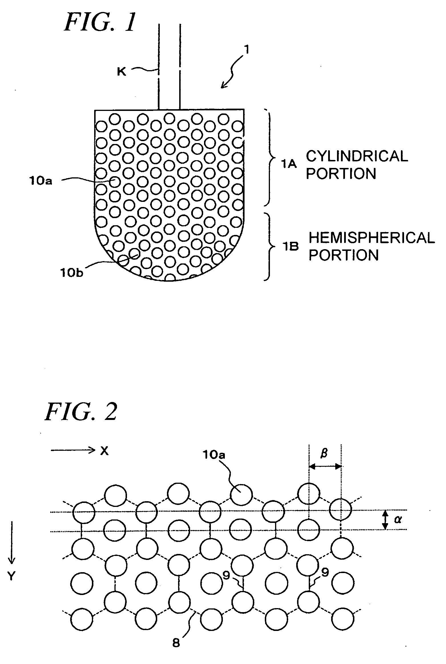
[0040]FIG. 1 is a front view of a transducer 1 according to a preferred embodiment of the invention. The transducer 1 is having an upper cylindrical portion 1A and a lower hemispherical portion 1B extending immediately downward from the cylindrical portion 1A. Designated by the letter K is a cable for transferring signals to and from a large number of transducer elements 10a, 10b which are arranged on the cylindrical portion 1A and the hemispherical portion 1B, respectively, according to later-described arrangement methods. Each of the transducer elements 10a, 10b is a vibrating element having a circular radiating face.

[0041]FIG. 2 is a view of a developed surface of the cylindrical portion 1A of the transducer 1 illustrating a method of arranging the transducer elements 10a on the cylindrical portion 1A of the transducer 1. As shown in FIG. 2, the transducer elements 10a are arranged in such a way that six transducer elements 10a adjacent to any one of the transducer elements 10a ...


PUM


Abstract

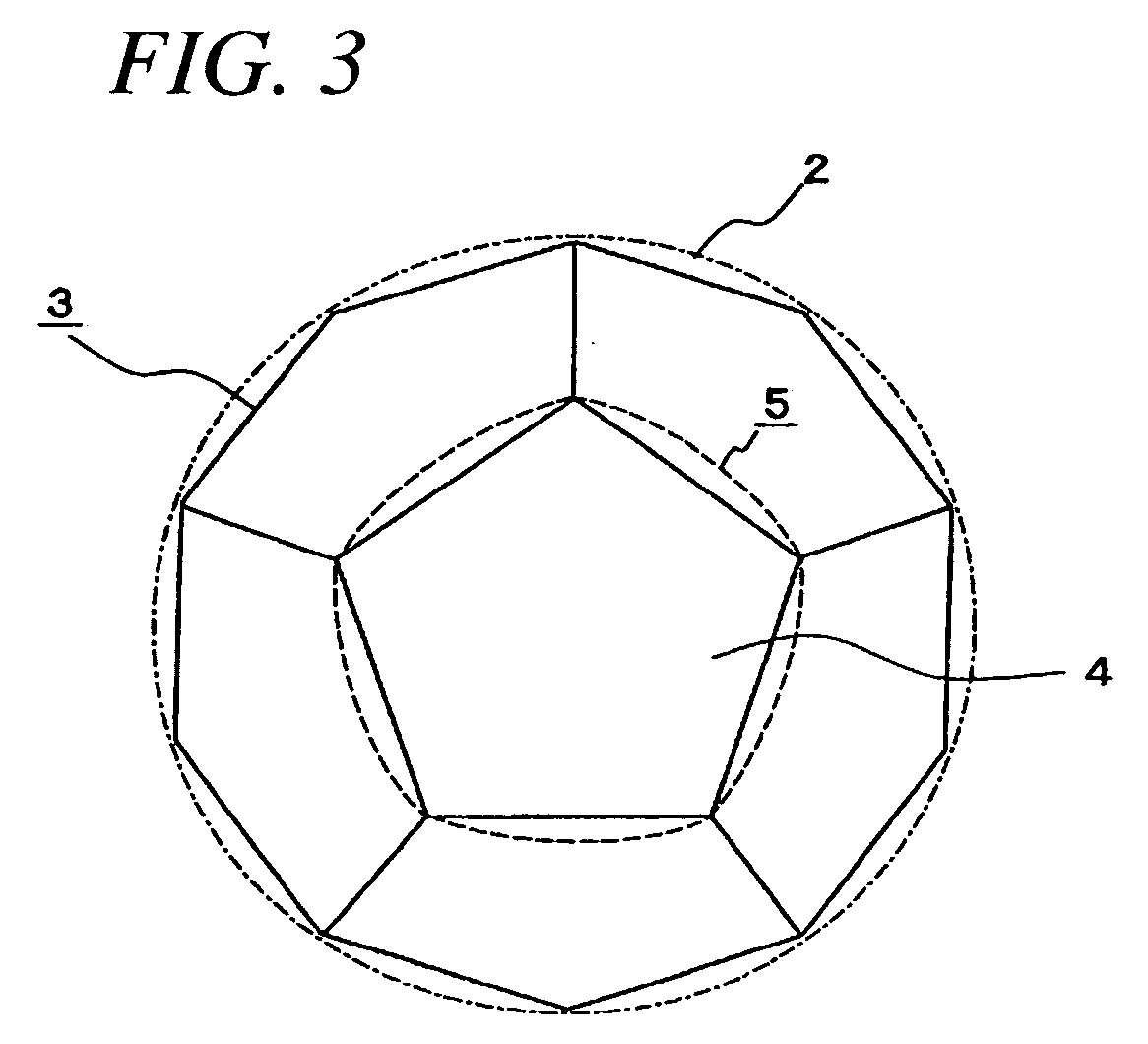
An acoustic transducer has an upper cylindrical portion and a lower hemispherical portion on which a plurality of transducer elements are arranged. The transducer elements on the cylindrical portion are arranged in such a way that six transducer elements adjacent to any one of the transducer elements are located at vertices of a regular hexagon and regular hexagons adjoining in a horizontal direction have sides which are oriented parallel to an axial direction (vertical direction) of the cylindrical portion. The transducer elements on the hemispherical portion are arranged at vertices of spherical triangles constituting each of spherical pentagons obtained by projecting regular pentagons together forming one half of a regular dodecahedron onto a hemispherical surface of the hemispherical portion in which the half of the regular dodecahedron is inscribed, as well as at equal division points taken on individual sides of each of the spherical triangles and at the centers of gravity of small spherical triangles formed at intersections of parallel arcs joining the equal division points of each of the spherical triangles.

Description

BACKGROUND OF THE INVENTION [0001] 1. Field of the Invention [0002] The present invention relates to an acoustic transducer and an underwater sounding apparatus for detecting underwater objects, such as fish schools, by use of ultrasonic waves. [0003] 2. Description of the Related Art [0004] Scanning sonars are conventionally known acoustic apparatuses for obtaining information on underwater objects, such as fish schools, distributed in a wide underwater area. A scanning sonar is provided with a transducer for transmitting an acoustic sounding beam in specific directions underwater and receiving echoes returned from underwater targets. There exist various types of sonar transducers, as illustrated in FIGS. 10 to 12, for example. [0005]FIG. 10 is a perspective view of a cylindrical transducer 50 used in a full-circle scanning sonar. The transducer 50 includes a large number of transducer elements 51 arranged in horizontal rows and vertical columns on a cylindrical side surface of the...

Claims


Application Information

Patent Timeline
IPC IPC(8): G10K11/00
CPCB06B1/0269B06B1/0622B06B1/0633B06B1/0637B06B2201/74G01S7/521G01S15/96G10K11/34G10K11/346G10K11/348H04R1/44G01S15/107G01S15/89H04R1/02G01S15/02
Inventor WATANABE, KENICHINISHIMORI, YASUSHITOKUYAMA, KOUZOTOKUDA, KOJISUETOSHI, RYOUICHI
Owner FURUNO ELECTRIC CO LTD
Why Eureka
Try Eureka