
Automatic determination of the control unit parameters of an arrangement to control an actuator for the adjustment of an adjustable element of an agricultural machine

an actuator and control unit technology, applied in the direction of adjusting devices, agricultural tools and machines, instruments, etc., can solve the problems of affecting the accuracy of the position of the height and lateral inclination affecting the accuracy of the position of the cutting unit, and affecting the performance of the cutting unit. , the degradation of performance may be so extrem

Active Publication Date: 2017-08-31
DEERE & CO
View PDF7 Cites 31 Cited by
  • Summary
  • Abstract
  • Description
  • Claims
  • Application Information

AI Technical Summary

Benefits of technology

The patent describes a system for automatically adjusting the control unit parameters of a work machine to improve its performance and driving comfort. The system uses a virtual model of the system, which is defined based on the adjustable element, the work machine, and the control arrangement and actuator dynamics. The system detects the vibration characteristics of the system and uses them to determine the parameters that characterize the model. An optimized parameters is then determined for the control unit and sent to it. This allows for a constant or regular adjustment of the control parameters based on the real-time behavior of the system, resulting in improved performance and driving comfort.

Problems solved by technology

This bouncing or twisting negatively affects the accuracy of the position of the height and the lateral inclination of the cutting unit.
Typically, however, the operator adjusts the control unit amplification only once for the whole day, which is then followed by a strong performance loss as the machine and field conditions change over time.
This degradation in performance may be so extreme that the operator is forced to reduce the machine's harvesting speed (i.e. the machine's speed over the ground) to prevent the vibrations (bouncing).
This speed reduction impairs the harvesting performance of the machine and reduces its productivity.
This control unit is suitable for the adjustment of the contact pressure, but not for the control of the height of a harvesting attachment or another element, since other parameters which characterize its movement behavior have to be determined for this.
The procedure is disadvantageous because the dead time and hysteresis represent only a few of the parameters of the control unit device to be appropriately controlled.
It is also disadvantageous because the iterative procedure is based exclusively on the detection of the adjustment signals of the control unit device, which works very indirectly, in a time-delayed manner and is thus subject to errors.

Method used


Image

  • Automatic determination of the control unit parameters of an arrangement to control an actuator for the adjustment of an adjustable element of an agricultural machine
  • Automatic determination of the control unit parameters of an arrangement to control an actuator for the adjustment of an adjustable element of an agricultural machine
  • Automatic determination of the control unit parameters of an arrangement to control an actuator for the adjustment of an adjustable element of an agricultural machine

Examples


first embodiment

of a Determination Device for the Stipulation of Parameters of the Control Unit

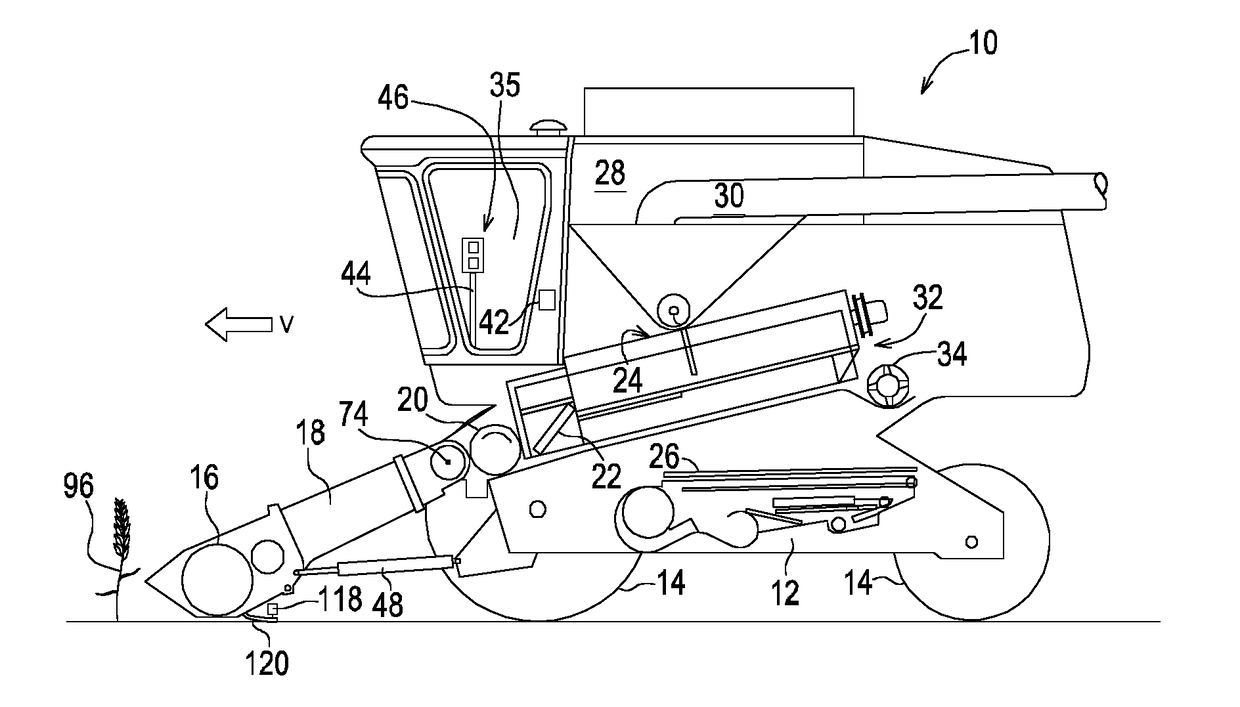
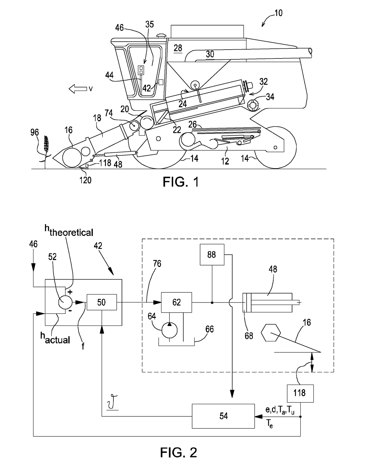
[0051]The control arrangement 42 of FIG. 2 comprises a determination device 54. In one arrangement, the determination device 54 is embodied as an electronic circuit comprising an ALU, RAM, and ROM, in which the RAM and / or ROM store digital instructions that configure the determination device 54 to perform the functions described herein. In another arrangement, the electronic circuit of the determination device 54 is separate from electronic circuit of the control unit 50. In another arrangement, a single electronic circuit is programmed to function as both the control unit 50 and the determination device 54.

[0052]The determination device 54 receives information indicating the adjustment signals of the actuator 48 from a pressure sensor 88. The pressure sensor 88 detects the pressure in the hydraulic fluid conduit that extends between the control device 62 and the piston chamber 68 of the actuator 48. And ...

second embodiment

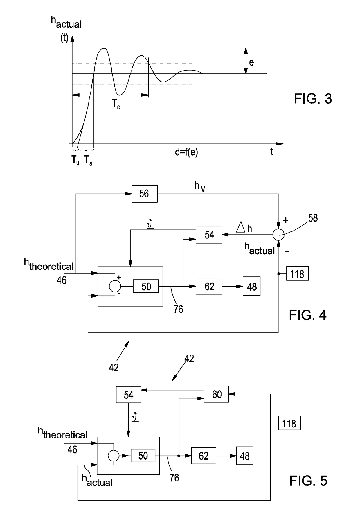
[0057]In the second embodiment of the control arrangement 42, shown in FIG. 4, elements corresponding to the first embodiment are marked with the same reference symbols. In this embodiment, the desired, ideal system behavior of the system consisting of the work machine 10 and the harvesting attachment 16 is described by a dynamic mathematical model 56 with the output hM. The deviation between the ideal system behavior and the real system behavior hactual is compared, with one another, by a subtractor 58 and the error Δh is given to the determination device 54. This calculates the new parameter vector θ of the control unit 50, in the sense of minimizing the deviation of the real behavior from the ideal behavior.

third embodiment

[0058]In the third embodiment of the control arrangement 42, shown in FIG. 5, elements corresponding to the first embodiment are marked with the same reference symbols. In this embodiment, an identification unit 60 is used, which determines the transfer characteristics of the control unit section, which consists of the control unit 62, the actuator 48, the system consisting of the work machine 10 and the harvesting attachment 16, and the height sensor 118, with the aid of an inlet signal (which is present on the output 76 of the control unit 50) and the output signal of the height sensor 118. With the aid of the transfer characteristics determined by the identification unit 60, the determination device 54 carries out a regulator design in accordance with known control unit-technical methods. The parameters θ of the control unit 50 are thus determined by an explicit controller design. A value representative for the transfer function of the control unit section can hereby be determine...


PUM


Abstract

An arrangement for the control of an actuator (48) for the adjustment of an adjustable element (16) of an agricultural work machine (10) is equipped with a control unit (50) to produce adjustment signals for the adjustable element (16) in the sense of moving to a theoretical position, a control arrangement (62) of the actuator (48), coupled with the adjustable element (16), which receives the adjustment signals of the control unit (50), and a determination device (54) to make available at least one parameter (0), determined with the aid of recorded vibration characteristics of the system consisting of the adjustable element (16) and the work machine (10). The determination device (54) can be operated so as to determine at least one parameter (0) at the successively following time points and to supply it to the control unit (50). The parameter (0) serves to optimize the regulating behavior of the control unit (50).

Description

FIELD OF THE INVENTION[0001]This application claims priority to German Application Ser. No. DE 102016202964.9 filed on Feb. 25, 2016, which is hereby expressly incorporated by reference in its entirety. The invention concerns an arrangement to control an actuator for the adjustment of an adjustable element of an agricultural machine.BACKGROUND OF THE INVENTION[0002]Generally, agricultural machines comprise elements that can be adjusted with respect to the frame or chassis of the machine by means of associated actuators—that is, they can be linear displaced or pivoted. In the case of a tractor, these elements can comprise a work device that is placed on a front or rear power lift of a tractor, for example, for the processing of the soil, for sowing, or to apply fertilizers or other chemicals—in the case of a self-propelled field sprayer, a height-adjustable spray rod and / or one which can pivot around an axis that extends in a fore-and-aft direction; with a harvester or a field choppe...

Claims


Application Information

Patent Timeline
Patent Type & Authority Applications(United States)
IPC IPC(8): A01D41/127A01B63/00G05B6/02A01D41/14
CPCA01D41/127G05B6/02A01B63/008A01D41/145A01B63/1006
Inventor JUNG, BENEDIKTMILLER, BYRON K.MUENCH, PHILIPP
Owner DEERE & CO
Learn More