Fiber optic cable having a dry insert and methods of making the same

Inactive Publication Date: 2006-07-27
CORNING OPTICAL COMM LLC
View PDF58 Cites 81 Cited by
  • Summary
  • Abstract
  • Description
  • Claims
  • Application Information

AI Technical Summary

Problems solved by technology

Cleaning the thixotropic material from the optical waveguide is a messy and time-consuming process.
Due to changing viscosity, the thixotropic materials can drip from an end of the tube at relatively high temperatures and the thixotropic materials may cause optical attenuation at relatively low temperatures.
Cable designs have attempted to eliminate thixotropic materials from the tube, but the designs are generally inadequate because they do not meet all of the requirements and / or are expensive to manufacture.
Consequently, conventional water-swellable tapes do not provide adequate coupling for the optical waveguides because of the unfilled space.
Thus, this design requires a large number of water-swellable components within the tube for adequately coupling the optical fibers with the tube.
Moreover, the use of large numbers of water-swellable components inside a buffer tube is not economical because it increases the manufacturing complexity along with the cost of the cable.

Method used


Image

  • Fiber optic cable having a dry insert and methods of making the same
  • Fiber optic cable having a dry insert and methods of making the same
  • Fiber optic cable having a dry insert and methods of making the same

Examples


Embodiment Construction

[0033] The present invention will now be described more fully hereinafter with reference to the accompanying drawings showing preferred embodiments of the invention. The invention may, however, be embodied in many different forms and should not be construed as limited to the embodiments set forth herein; rather, these embodiments are provided so that the disclosure will fully convey the scope of the invention to those skilled in the art. The drawings are not necessarily drawn to scale but are configured to clearly illustrate the invention.

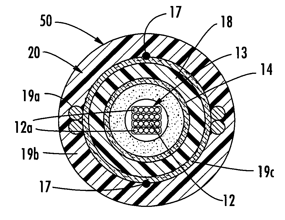
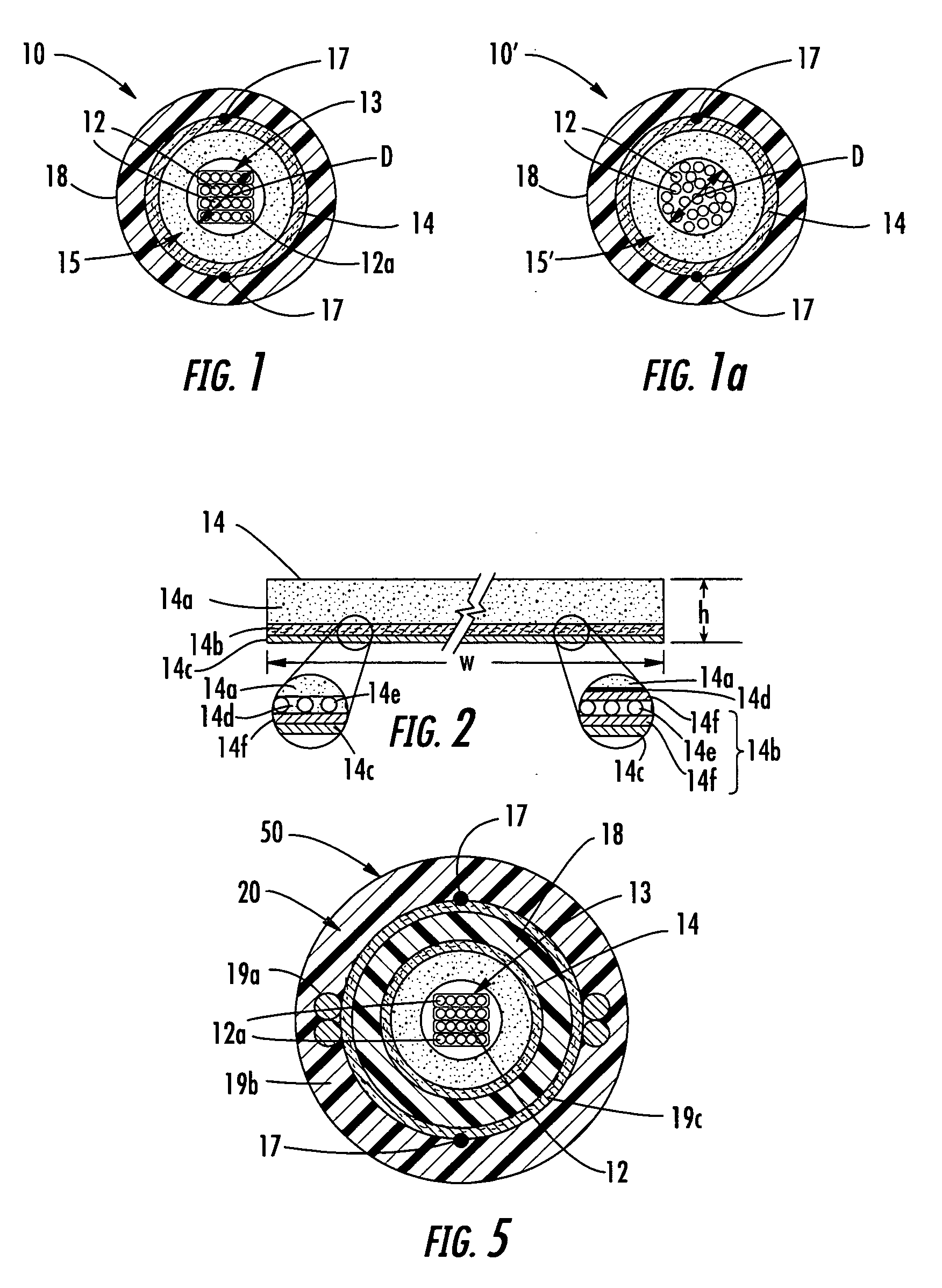
[0034] Illustrated in FIG. 1 is an exemplary tube assembly 10 according to one aspect of the present invention. Tube assembly 10 includes at least one optical waveguide 12 such as an optical fiber, at least one dry insert 14, and a tube 18. In this case, the at least one optical waveguide 12 is in the form of a stack of ribbons 13 having a diagonal D dimension across the corners of the stack. Dry insert 14 generally surrounds the at least one opti...


PUM


Abstract

A fiber optic cable and a method of making the same include at least one optical waveguide, at least one dry insert and a cable jacket. The at least one optical waveguide and at least one dry insert are at least partially disposed within a cavity of the cable jacket. In one embodiment, the cable includes a first dry insert and a second dry insert disposed within the cavity so that the at least one optical waveguide is disposed between the first dry insert and the second dry insert.

Description

RELATED APPLICATIONS [0001] The present application is a Continuation-In-Part (CIP) of U.S. Ser No. 10 / 862,541 filed on Jun. 7, 2004, which is a Continuation-In-Part of U.S. Ser. No. 10 / 847,807 filed on May 18, 2004, which is a Continuation-In-Part of U.S. Ser. No. 10 / 661,204 filed on Sep. 12, 2003, which is a Continuation-In-Part of U.S. Ser. No. 10 / 326,022 filed on Dec. 19, 2002, the disclosures of which are incorporated herein in their entirety by reference.FIELD OF THE INVENTION [0002] The present invention relates generally to dry packaging of optical waveguides. More specifically, the invention relates to optical assemblies for communication systems that include at least one dry insert for protecting at least one optical waveguide. BACKGROUND OF THE INVENTION [0003] Fiber optic cables include optical waveguides such as optical fibers that transmit optical signals, for example, voice, video, and / or data information. One type of fiber optic cable configuration includes an optica...

Claims


Application Information

Patent Timeline
IPC IPC(8): G02B6/44
CPCG02B6/4403G02B6/4433G02B6/4483G02B6/4494G02B6/44384
Inventor GREENWOOD, JODY L.TEMPLE, KENNETH D. JR.LAIL, KEITH H.SEDDON, DAVID A.TUTTLE, RANDALL
Owner CORNING OPTICAL COMM LLC
Why Eureka
Try Eureka