Tissue structure identification in advance of instrument

a tissue structure and tissue technology, applied in the direction of instruments, catheters, incision instruments, etc., can solve the problems of severing injury, affecting the sensation or motion control of biopsy patients, and often damaging important tissue inadvertently

Inactive Publication Date: 2011-10-25
CLARKE DANA S
View PDF20 Cites 141 Cited by
  • Summary
  • Abstract
  • Description
  • Claims
  • Application Information

AI Technical Summary

Benefits of technology

[0015]In one embodiment, the medical instrument is a needle for extracting body fluid or injecting medication. The optical fiber is embedded in the needle longitudinally thereof. Multiple fibers may be used to provide improved information content. In another embodiment one or more optical fibers are embedded in a scalpel. Preferably, the wavefront analysis system is an OCDR system, but other means for analyzing the wavefront information could be used.

Problems solved by technology

During surgery important tissue is often damaged inadvertently.
For example, biopsy patients often report a loss of sensation or motion control due to nerve damage sustained during surgery.
Another current medical problem occurs during tests of certain body fluids or during localized injections, where a needle used to extract body fluids or inject medication must penetrate one body structure without penetrating a subsequent structure.
For example, in performing a spinal tap it is desirable to penetrate the dural membrane containing the spinal fluid, but highly undesirable to penetrate, or even touch the spinal cord itself as that can cause sever injury and potentially permanent paralysis.
Yet, this is generally carried out without the aid of any means for seeing the physical relationship of the tip of the spinal tap needle to the spinal structures or even a way of measuring the distance from the tip to structure that must not be penetrated.
Similarly, in carotid injections in small laboratory animals it is often difficult to find the artery or vein in small animals, and it can be very difficult to keep from penetrating entirely through the artery or vein, once it is found.
This can make drug delivery excessively time consuming and difficult to control.
However, the usefulness of this technique is limited by the size and vulnerability of the lens assembly associated with the test fiber.
Like Swanson et al., the disclosure of Tearney et al. is limited by the use of an optical system at the distal end of the test fiber, and it is static with respect to tissue depth.
While in-line tomography, that is, obtaining OCDR data relative to various locations along the axis of propagation of the OCDR light is disclosed, this system is limited to use with a non physically invasive laser tool applied to the eye, which is especially adapted for light transmission, and is limited by the use of large, free-space optics for coupling the OCDR into the eye.
However, it is limited in applicability by the size of the endoscope and distal optics.
This information, referred to as feedforward, is much harder information to acquire.
Combining this information with basic anatomy information can let the robot know where and what it is cutting and to estimate what it is cutting, but does not allow the robot actually to sense the tissue that is being cut or to sense ahead of the cut.
However, neither of these techniques has sub-millimeter resolution.
So, for delicate work they are not optimal.
In addition, MRI is severely constrained in application by its size, its cost, and the strength of the magnets involved.
Ultrasound has considerably worse spatial resolution than MRI.

Method used


Image

  • Tissue structure identification in advance of instrument
  • Tissue structure identification in advance of instrument
  • Tissue structure identification in advance of instrument

Examples


Embodiment Construction

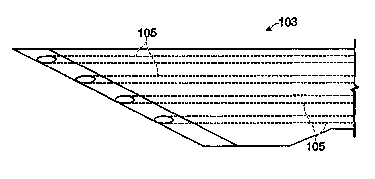
[0033]The method and apparatus of the present invention uses optical fibers aligned along a needle, scalpel or other mechanical cutting tool to both transmit and receive optical information directly in front of the cutting surface. OCDR is used to determine the depth of boundaries immediately in advance of a cutting surface such as a needle tip or scalpel blade. This information can be used to alert either a medical professional or a surgical robot to the presence of an upcoming boundary and possibly identify the tissue.

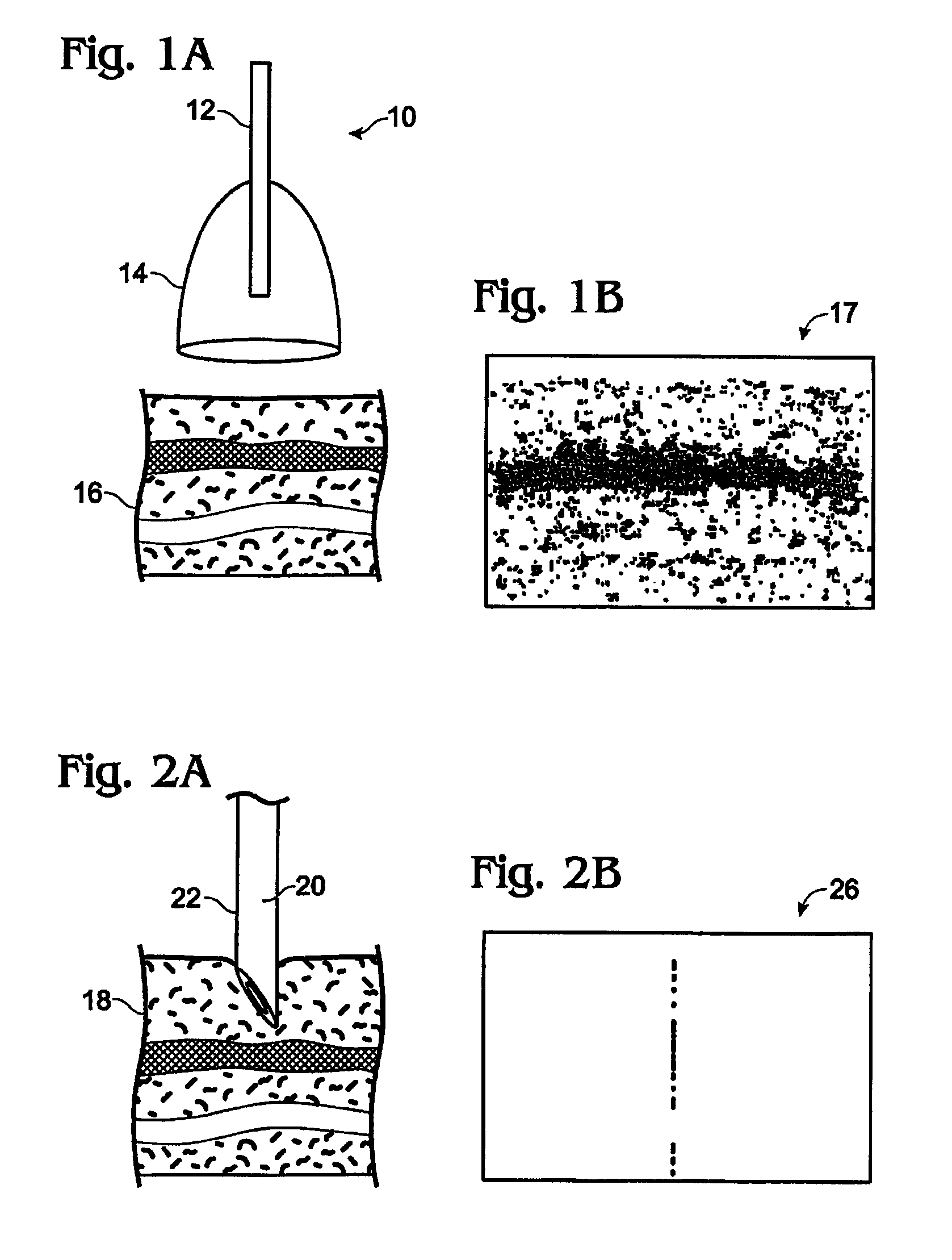
[0034]The basic concept of prior art OCT 10 is illustrated by FIGS. 1(a) and 1(b), which shows a typical test fiber 12 and associated distal optic 14 in relation to a tissue sample 16 to be scanned. This prior art system, which does not mechanically penetrate the tissue, can produce a two-dimensional tomographic image 17 of relatively limited depth of, for example, 1-2 millimeters.

[0035]In contrast, the apparatus for identifying tissue structures ahead of a mechanica...


PUM

PropertyMeasurementUnit
depthaaaaaaaaaa
diameteraaaaaaaaaa
diameteraaaaaaaaaa

Abstract

A method and apparatus for identifying tissue structures in advance of a mechanical medical instrument during a medical procedure. A mechanical tissue penetrating medical instrument (22) has a distal end for penetrating tissue in a penetrating direction. An optical wavefront analysis system (32-50) provides light to illuminate tissue ahead of the medical instrument and receives light returned by tissue ahead of the medical instrument. An optical fiber (30) is coupled at a proximal end to the wavefront analysis system and attached at a distal end to the medical instrument proximate the distal end of the medical instrument. The distal end of the fiber has an illumination pattern directed substantially in the penetrating direction for illuminating the tissue ahead of the medical instrument and receiving light returned therefrom. The wavefront analysis system provides information about the distance from the distal end of the medical instrument to tissue features ahead of the medical instrument.

Description

RELATED APPLICATION[0001]This application is based on provisional patent application No. 60 / 283,068, filed Apr. 11, 2001, and hereby incorporated by reference in its entirety.FIELD OF THE INVENTION[0002]This invention relates to medical procedures and apparatuses for performing medical procedures and, in particular, to methods and apparatuses for identifying tissues structures in advance of a tissue penetrating medical instrument.BACKGROUND OF THE INVENTION[0003]During invasive medical procedures employing a tissue penetrating medical instrument, such as a needle or a scalpel, there is a need to identify tissue structures in advance of the medical instrument so as to control the depth of penetration of the tip or cutting edge of the medical instrument. This may be done to ensure that the penetration is to the right depth, but usually more importantly, this is done to ensure that the medical instrument does not penetrate too deeply and thereby damage tissue structure unnecessarily.[0...

Claims


Application Information

Patent Timeline
Patent Type & Authority Patents(United States)
IPC IPC(8): A61B5/00A61B17/00A61B17/32A61B17/34A61B19/00G01N21/85
CPCA61B5/0066A61B5/0084A61B5/6848A61B5/6849A61B17/3211A61B17/34G01N21/8507A61B19/5225A61B2017/00061A61B2019/461A61B2019/462A61B2019/5206A61B2019/5217A61B2562/0242A61B2090/3614A61B2090/061A61B2090/062A61B2090/306A61B90/37
Inventor CLARKE, DANA S.
Owner CLARKE DANA S
Why Eureka
Try Eureka