Electrically tunable diffractive grating element

a technology of diffractive grating and electric tunable, which is applied in the direction of diffraction gratings, optics, instruments, etc., can solve the problems of the most serious effect of color non-uniformity, and achieve good color uniformity and high image quality

Active Publication Date: 2007-02-27
MAGIC LEAP
View PDF9 Cites 150 Cited by
  • Summary
  • Abstract
  • Description
  • Claims
  • Application Information

AI Technical Summary

Benefits of technology

[0030]The main purpose of the current invention is to present a novel, electrically tunable diffractive grating element. This device according to the invention is especially suitable for beam expansion purposes for example in EPEs and virtual display devices, and does not suffer from the a

Problems solved by technology

In prior art solutions the color non-uniformity increases along the length of the diffractive element H, because for those light waves

Method used


Image

  • Electrically tunable diffractive grating element
  • Electrically tunable diffractive grating element
  • Electrically tunable diffractive grating element

Examples


Embodiment Construction

[0042]It is to be understood that the drawings mentioned briefly above and described more fully below are designed solely for purposes of illustration and thus, for example, not for showing the various components of the devices in their correct relative scale and / or shape. For the sake of clarity, the components and details which are not essential in order to explain the spirit of the invention have been omitted in the drawings.

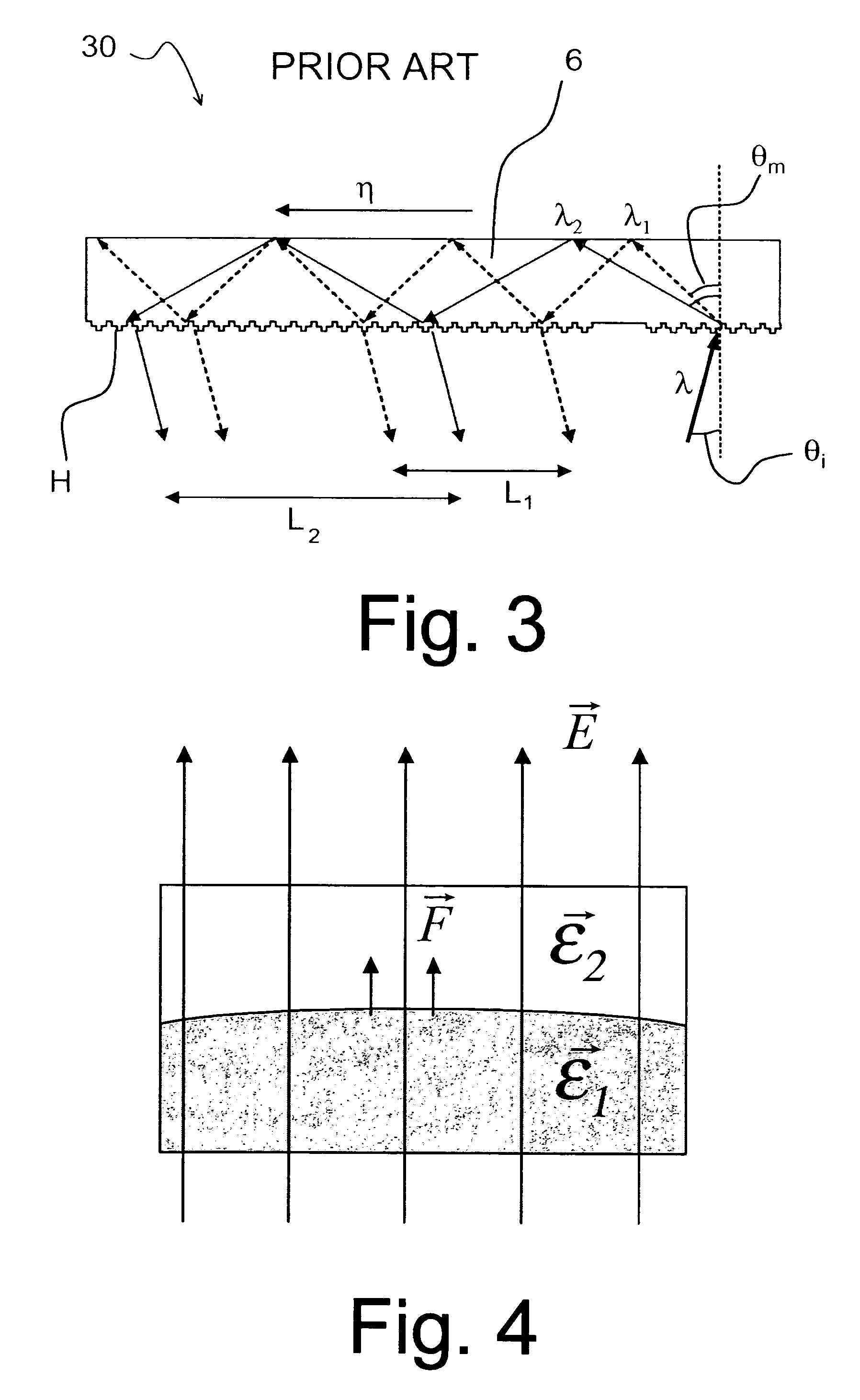
[0043]FIG. 4 illustrates schematically the general principle in physics, which can be observed in connection with dielectric substances. “Dielectric substance” can be defined as a substance in which an electric field may be maintained with zero or near zero power dissipation, i.e. the electrical conductivity of the substance is zero or near zero. An electric field E going through an interface where the dielectric constant changes, such as at the interface between air and polymer, causes a force F onto the surface of the dielectric material having the higher d...


PUM


Abstract

The invention relates to an optical device (50) for manipulating a light wave (λ) using a diffractive grating structure (G). According to the basic idea behind the invention a prior art type diffractive grating structure having a permanently shaped surface relief is substituted with an electrically deformable diffractive grating structure (G), where a preformed, basic surface relief of the grating is composed of dielectric and deformable viscoelastic material, which can be electrically and sequentially fine tuned in shape to adjust the diffraction properties of said grating individually for different wavelengths. The invention permits manufacture of virtual display devices with a significantly larger exit pupil diameter than prior art solutions without degrading the color uniformity of the display device.

Description

CROSS-REFERENCE TO RELATED APPLICATIONS[0001]This application claims priority under 35 USC §119 to Finnish Patent Application No. 20021669 filed on Sep. 19, 2002.[0002]1. Field of the Invention[0003]The present invention relates to an electrically tunable optical diffractive device comprising a light-transmittive substrate for guiding a light wave within the substrate and a diffractive grating structure carried by said substrate and arranged to couple the energy of the light wave between the substrate and the surroundings.[0004]2. Background of the Invention[0005]Display technology is one of the key elements in current development of new portable devices, which today typically feature wireless connectivity for voice and data access—and that will include a display for viewing, for example, text, graphics and different types of multimedia. The displays of such portable devices need to be increasingly capable of reproducing high quality color still images and also live color video. Suc...

Claims


Application Information

Patent Timeline
IPC IPC(8): G02B6/34G02B6/26G02B5/18G02B26/08
CPCG02B5/1828G02B27/0081G02B26/0808
Inventor LEVOLA, TAPANI
Owner MAGIC LEAP
Why Eureka
Try Eureka