Backlight unit and liquid crystal display device using the same

a backlight unit and liquid crystal display technology, applied in the field of backlight units and liquid crystal display devices, can solve the problems of less advantageous color reproducibility of lcd than crt, inability to meet the demand for electronic products having a reduced size and weight, and inability to light lamps in direct type backlights, etc., to achieve the effect of improving color uniformity and color mixtur

Inactive Publication Date: 2006-09-14
LG DISPLAY CO LTD
View PDF10 Cites 25 Cited by
  • Summary
  • Abstract
  • Description
  • Claims
  • Application Information

AI Technical Summary

Benefits of technology

[0026] Another object of the present invention is to provide a backlight unit and LCD device using the same that can prevent the LED lamp from being broken or deformed forming the reflecting substance on each LED lamp.
[0027] Still another object of the present invention is to provide a backlight unit and LCD device using the same that can improve color uniformity and color mixture by reflecting light emitted from the LED lamps in the lateral directions.

Problems solved by technology

However, the CRT cannot meet the demand for an electronic product having a reduced size and weight.
Hence, it is possible that some of the lamps in the direct type backlight are not lighted due to the failure or long-term use endurance of the lamps.
Despite its physical advantages of lightweight, flatness, smallness and shortness, the LCD is less advantageous than the CRT in color reproducibility, luminance and the like.
When blue, green and red LEDs are simultaneously used in implementing a white color, many problems take place in its application.
In particular, its application is substantially difficult due to the technical difficulty of producing the white color by collecting different colors coming from locations of the respective LEDs.
However, if they are removed, the light coming from the upper part of the LED lamps 31 directly propagate to the diffuser sheet to fail in being mixed together, thereby degrading the light uniformity.

Method used


Image

  • Backlight unit and liquid crystal display device using the same
  • Backlight unit and liquid crystal display device using the same
  • Backlight unit and liquid crystal display device using the same

Examples


Embodiment Construction

[0042] Reference will now be made in detail to the preferred embodiments of the present invention, examples of which are illustrated in the accompanying drawings. Wherever possible, the same reference numbers will be used throughout the drawings to refer to the same or like parts.

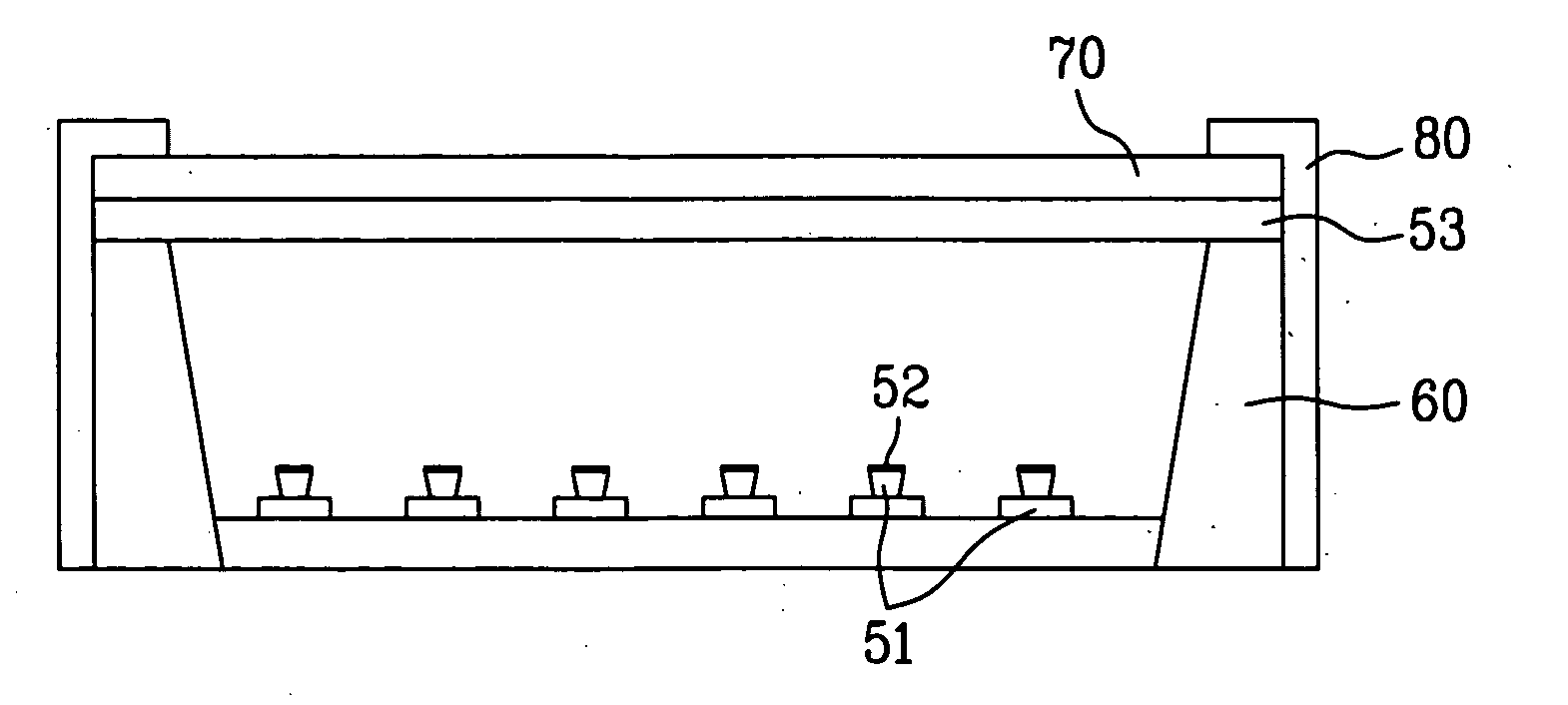
[0043]FIG. 5 is a layout view schematically illustrating a backlight unit according to one exemplary embodiment of the present invention, and FIG. 6A and FIG. 6B are cross-sectional views schematically illustrating the backlight unit taken along cutting lines III-III′ and IV-IV′ of FIG. 5. As showing in FIG. 5, FIG. 6A and FIG. 6B, a direct type LED backlight unit includes a plurality of lamp array units 50, each having a plurality of R / G / B LED lamps 51 sequentially arranged in one direction, a reflecting substance 52 formed on an upper surface of each of the LED lamps 51 to reflect light in a lateral direction, a light dispersion member 53 provided over the lamp array units 50 for diffusing to transfer th...


PUM

PropertyMeasurementUnit
transparentaaaaaaaaaa
light dispersionaaaaaaaaaa
coloraaaaaaaaaa

Abstract

A backlight unit includes a plurality of lamp array units, each having a plurality of LED lamps evenly arranged in one direction, a reflecting substance formed on an upper surface of each of the LED lamps to reflect light emitted from the corresponding LED lamp in a lateral direction, a light dispersion member provided over the lamp array units, and an outer case supporting the light dispersion member.

Description

[0001] This application claims the benefit of the Korean Patent Application No. P2005-0017029, filed in Korea on Feb. 28, 2005, which is hereby incorporated by reference. BACKGROUND OF THE INVENTION [0002] 1. Field of the Invention [0003] The present invention relates to a liquid crystal display (LCD) device, and more particularly, to a backlight unit and LCD device using the same. Although the present invention is suitable for a wide scope of applications, it is particularly suitable for improving uniformity and color mixture of the backlight. [0004] 2. Discussion of the Related Art [0005] Generally, a cathode ray tube (CRT) is mainly used as one of various display devices, such as a monitor of a television (TV), measuring instrument, information terminal or the like. However, the CRT cannot meet the demand for an electronic product having a reduced size and weight. For this reason, many flat display devices, such as an LCD using electric-field optical effect, a plasma display pane...

Claims


Application Information

Patent Timeline
Patent Type & Authority Applications(United States)
IPC IPC(8): G02F1/1335F21S2/00F21V5/00F21V7/00F21Y101/02G02F1/13357
CPCG02F1/133603F24C3/008F24C15/107
Inventor BANG, JU YOUNG
Owner LG DISPLAY CO LTD
Why Eureka
Try Eureka