Color filter for liquid crystal displays

a liquid crystal display and color filter technology, applied in the field of color filter for liquid crystal displays, can solve the problems of inability to use color filters, inability to achieve comparable results, and inability to control coating thickness, etc., to achieve enhanced color uniformity, reduce coating thickness, and improve color uniformity

Inactive Publication Date: 2001-03-20
KYODO INSATU KK KYODO PRINTING CO LTD
View PDF32 Cites 25 Cited by
  • Summary
  • Abstract
  • Description
  • Claims
  • Application Information

AI Technical Summary

Benefits of technology

A calculation based on a refraction index of 1.8 of the resin of the colored patterns reveals that a difference in coating thickness causing an occurrence of absorption maximum and absorption minimum due to interference of light at the same wavelength is 0.0625 .mu.m at 450 nm. If the coating thickness is varied to this extent, interference occurs in the light transmission regions to cause the color filter to become darker by about 10%. An allowable range of: the coating thickness for causing an occurrence of interference is essentially be a half or less of this difference in coating thickness. This can be obtained by the following calculation. 0.0625.times.0.5 / 0.05=0.625 .mu.m. In consideration of the range of refraction index of the resin used in the colored patterns, the coating thickness of the colored patterns forming the color filter must be 0.7 .mu.m or less all the same. It goes without saying that the coating thickness can be controlled more effectively as the coating thickness is more reduced, and uniformity of color is enhanced.

Problems solved by technology

It was known through experiments that a mere application of dye, which was supposed to have good light resistance, to a colorant of a color filter used in a reflection type liquid crystal display device results in inferior light resistance, thus making such a color filter entirely unusable.
However, no comparable findings are so far obtained in such a special circumstance as in a state of no oxygen as in a liquid crystal display device, where a general common knowledge is not applicable.

Method used


Image

  • Color filter for liquid crystal displays
  • Color filter for liquid crystal displays
  • Color filter for liquid crystal displays

Examples


Embodiment Construction

/ Industrial Applicability of the Invention

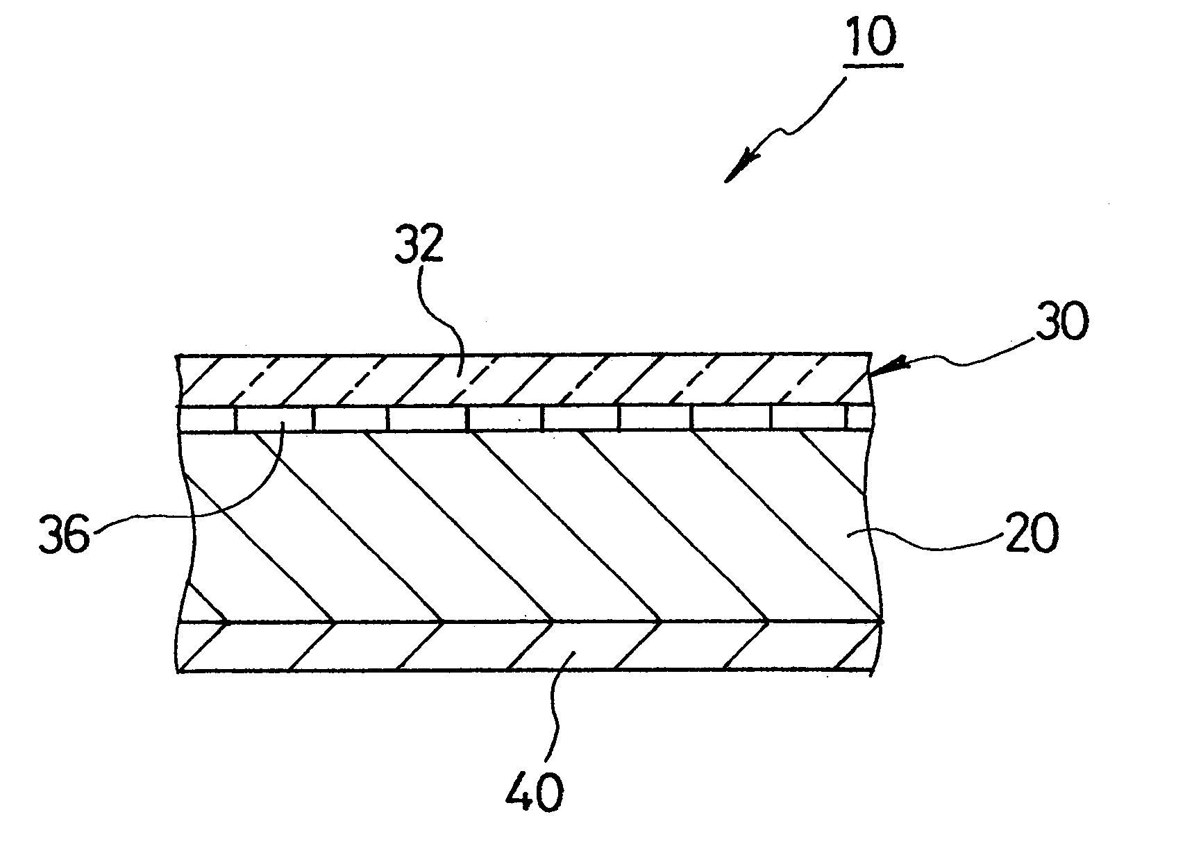
FIG. 1 shows a sectional construction of a reflection type color liquid crystal display device including a color filter. The color liquid crystal display device 10 includes a color filter disposed on one surface of a host guest liquid crystal 20 and a reflection layer 20 on the other surface. The color filter itself is comprised of a transparent substrate 40 such as a sheet of glass and a color filter layer 36 including colored patterns consisting of three colors YMC (yellow, magenta and cyan) formed on the substrate 32. The respective colored patterns of the color filter layer 36 can be formed, for example, by a photolithographic technique which is well known in the art for manufacturing a transmission type color filter.

The composition, coating thickness and minimum transmission factor of each YMC-based color pattern was set as indicated hereinafter and each colored pattern was exposed to light using a carbon arc fade meter for 100 hours an...


PUM

PropertyMeasurementUnit
transparentaaaaaaaaaa
thicknessaaaaaaaaaa
thicknessaaaaaaaaaa

Abstract

A reflection-type color filter (30) is disclosed, in which light coming into one surface of a color filter layer (36) is reflected by a reflective layer (40) and allowed to pass through the color filter layer (36) twice. Colored patterns of the color filter layer (36) include resin such as polyimide and dye for dyeing the resin. The thickness of the colored patterns is 0.7 mum or less. In order to enhance light resistance, it is effective to increase the content of dye with respect to resin. The value of 0.7 mum is established in consideration of enhancement of optical characteristic and light resistance of the color filter used in the reflection type liquid crystal display device. In order to enhance light resistance, more preferably, a metal complex is added to the resin.

Description

This invention relates to a color filter for displaying an image in color on a liquid crystal display device, and more particularly to a color filter of the type in which color density is thin and dye is used as a colorant.BACKGROUND OF INVENTIONAs a method for producing a color filter used in a liquid crystal display device, there are known methods for applying a color using pigment, such as a pigment dispersing method or an electrodeposition method, and for applying a color(s) using dye, such as a dyeing method or a dye dissolution method. Usually, a color filter layer consists or three primary colors, red, green and blue. The colored patterns of the color filter layer having a coating thickness of 1 to 2 .mu.m are formed in a mosaic pattern or in a stripe pattern.In general, it is said that although dye is superior in transparency and purity of color and more abundant in kind compared with pigment, the former is inferior in light resistance to the latter. Also, it is known that c...

Claims


Application Information

Patent Timeline
Patent Type & Authority Patents(United States)
IPC IPC(8): G02F1/13G02B5/20G02F1/1335
CPCG02B5/201G02F1/133514
Inventor FURUKAWA, TADAHIROMURAI, TATSUHIKOTAKAHASHI, ATSUSHI
Owner KYODO INSATU KK KYODO PRINTING CO LTD
Why Eureka
Try Eureka