

Capacitive touch panel
a capacitive touch panel and capacitive technology, applied in the field of capacitive touch panels, can solve the problems of color cast problem, deterioration of jeopardizing the aesthetics, so as to improve the display quality of the capacitive touch panel, reduce the gap between the sensing unit and increase the color uniformity
- Summary
- Abstract
- Description
- Claims
- Application Information
AI Technical Summary
Benefits of technology
Problems solved by technology
Method used
Image

Examples
first embodiment
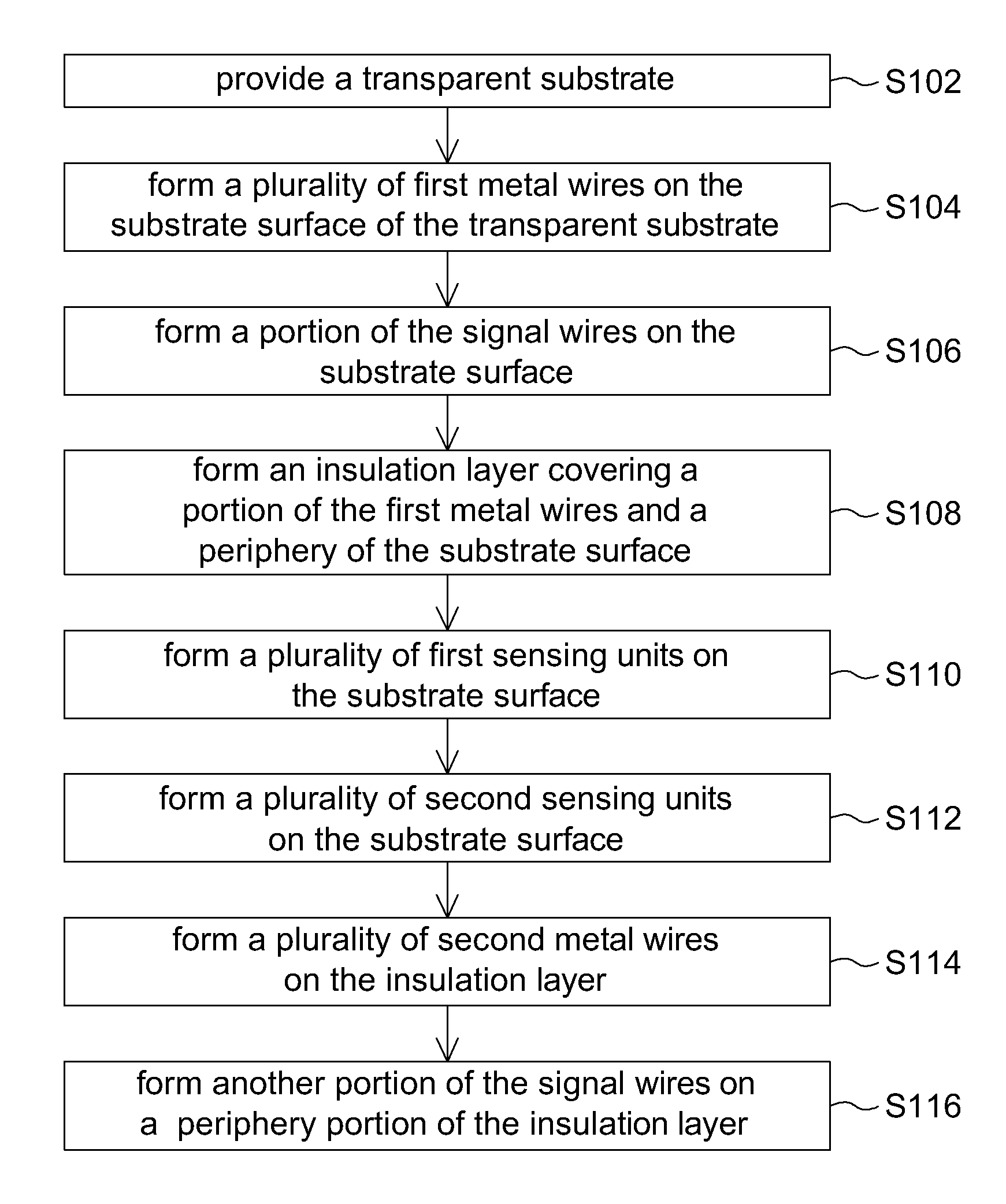
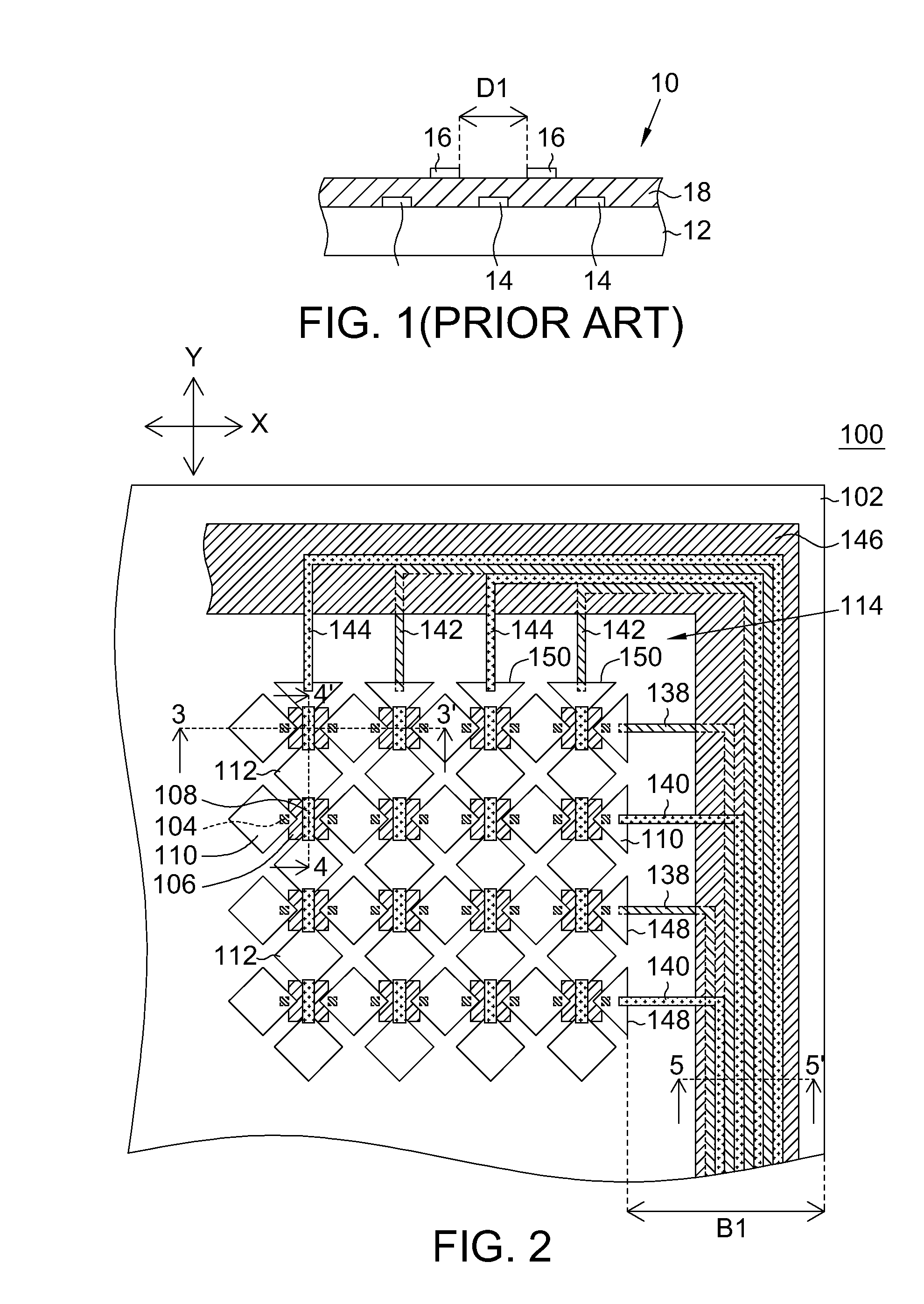
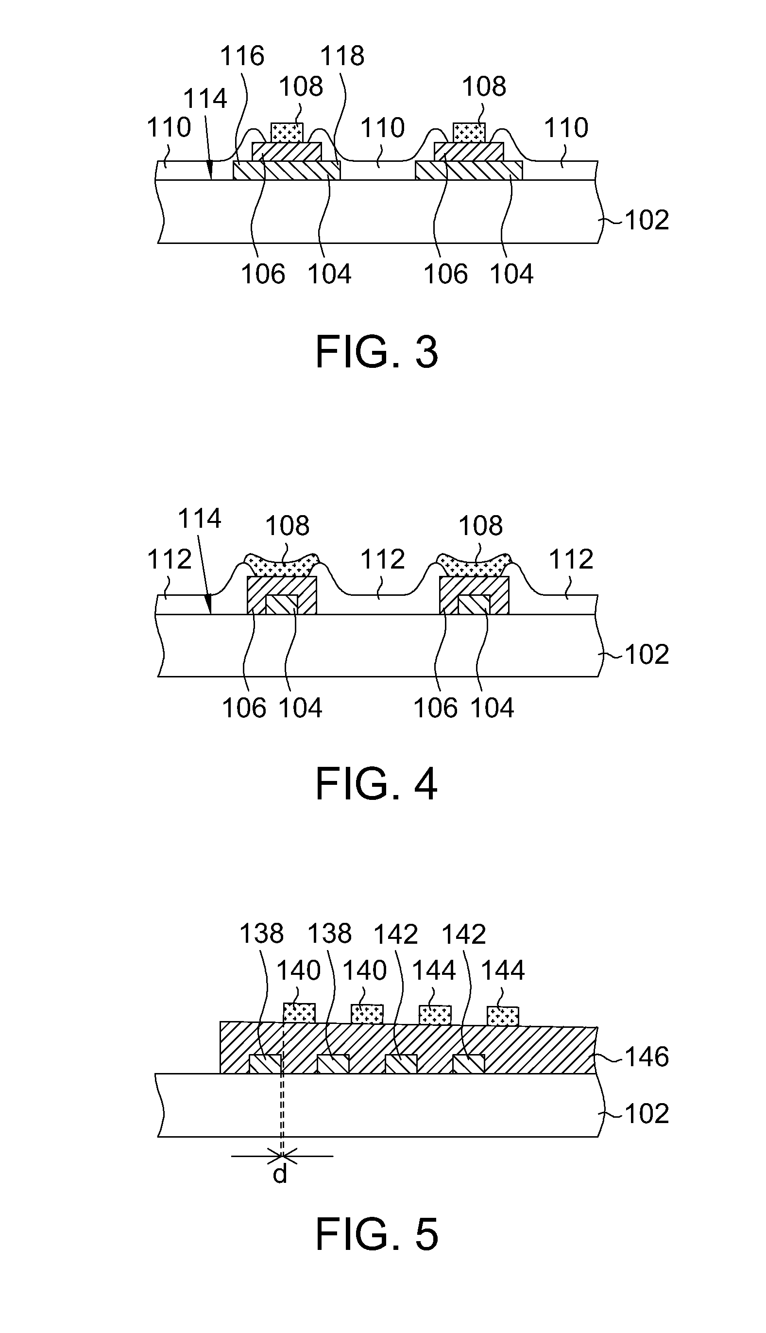
[0038]Referring to FIG. 2, a top view of a capacitive touch panel according to the first embodiment of the invention is shown. The capacitive touch panel 100 includes a transparent substrate 102, a plurality of first metal wires 104, an insulation layer 106, a plurality of second metal wires 108, a plurality of first sensing units 110 and a plurality of second sensing units 112. The transparent substrate 102 further has a substrate surface 114. The transparent substrate 102 can be formed by an insulating material with high transmittance such as glass, polycarbonate (PC), polythylene terephthalate (PET), polymethylmethacrylate (PMMA) and cyclic olefin copolymer.
[0039]The first sensing units 110 and the first metal wires 104 are arranged as a plurality of first sensing wires 148, wherein each first sensing wire 148 is arranged along a first direction such as the X-axial direction. The second sensing units 112 and the second metal wires 108 are arranged as a plurality of second sensing...
second embodiment
[0064]Referring to both FIG. 8 and FIG. 9, a cross-sectional view of a capacitive touch panel according to the second embodiment of the invention is respectively shown. As for the similarities between the second embodiment and the first embodiment, the same designations are used, and the similarities are not repeated here. The capacitive touch panel 200 of second embodiment is different from the capacitive touch panel 100 of the first embodiment in that, the capacitive touch panel 200 further includes an optical film 202.
[0065]The optical film 202 is formed on the substrate surface 114 and covers the first metal wires 104, the insulation layer 106, the first sensing units 110, the second sensing units 112 (not illustrated) and the second metal wires 108. The optical film 202 increases light transmittance. Preferably, the refractive index of the optical film 202 is smaller than 1.7. The optical film 202 can be formed by materials including silicon oxide, magnesium fluoride, aluminum ...
third embodiment
[0066]Referring to FIG. 10, a top view of a capacitive touch panel according to the third embodiment of the invention is shown. As for the similarities between the third embodiment and the first embodiment, the same designations are used, and the similarities are not repeated here. The capacitive touch panel 300 of the third embodiment is different from the capacitive touch panel 100 of the first embodiment in that, the signal wires of the capacitive touch panel 300 have a bending shape.
[0067]In greater details, as indicated in FIG. 10, the capacitive touch panel 300 includes a plurality of signal wires, such as a plurality of first signal wires 322 and a plurality of second signal wires 330.
[0068]One end of the first signal wire 322 is electrically connected to the corresponding first sensing wire 148, and the other end of the first signal wire 322 is electrically connected to a signal output cable (not illustrated).
[0069]Each first signal wire 322 includes a first sub-signal wire ...
PUM
 Abstract
Description
Claims
Application Information