Sub-malleolar non-articulating prosthetic foot with improved dorsiflexion

a non-articulating, foot technology, applied in the field of foot prostheses, can solve the problems of limited use, high cost and complexity of these devices, and the sole plate does not have enough flexibility to allow for a natural gait, so as to improve the dorsiflexion of the prosthetic foot, the effect of reducing the stiffness of the overall par

Inactive Publication Date: 2006-07-27
COLLEGE PARK IND INC
View PDF35 Cites 28 Cited by
  • Summary
  • Abstract
  • Description
  • Claims
  • Application Information

AI Technical Summary

Benefits of technology

[0008] A prosthetic foot includes a sole plate having a body formed of resilient material of lower material stiffness or overall part stiffness than is typical to the art. The sole plate is elongated along an anterior and posterior axis wherein an anterior portion of the plate defines a toe portion and the posterior portion defines a heel portion. An ankle member having a planar portion in contact with the sole plate is rigidly affixed to the sole plate at the heel portion. The ankle member has an extension portion positioned anterior of the planar portion and separated from the planar portion by a transition portion. A resilient pad is disposed between the contact portion of the ankle member and the sole plate. The resilient pad and extension portion of ankle member define a gap such that as a user's weight is transferred anterior following initial contact, the extension portion of the ankle member tilts forward reducing the gap formed between the resilient pad and the extension portion for improving the dorsiflexion of the prosthetic foot while simultaneously retaining the critical requirement of durability by arching the sole plate about the resilient pad, distributing sole plate internal stresses.

Problems solved by technology

Many of these devices are mechanically complex and employ a number of moving parts.
While such devices provide extremely good and reliable performance characteristics, their cost and complexity limits their use, particularly in high volume applications and in user communities which do not have a sophisticated technical infrastructure to support and maintain such devices.
However, such rigid materials can lead to problems in that the sole plate does not have sufficient flexibility to allow for a natural gait.
Very rigid materials or thicknesses of materials may promote durability but do not flex to allow the heel of the sole plate to maintain contact with the ground surface a sufficient period of time to approximate a natural foot action.
Such premature heel rise leads to a less natural gait of a user of the prosthetic device, with increased mental and physical fatigue.

Method used


Image

  • Sub-malleolar non-articulating prosthetic foot with improved dorsiflexion
  • Sub-malleolar non-articulating prosthetic foot with improved dorsiflexion
  • Sub-malleolar non-articulating prosthetic foot with improved dorsiflexion

Examples


Embodiment Construction

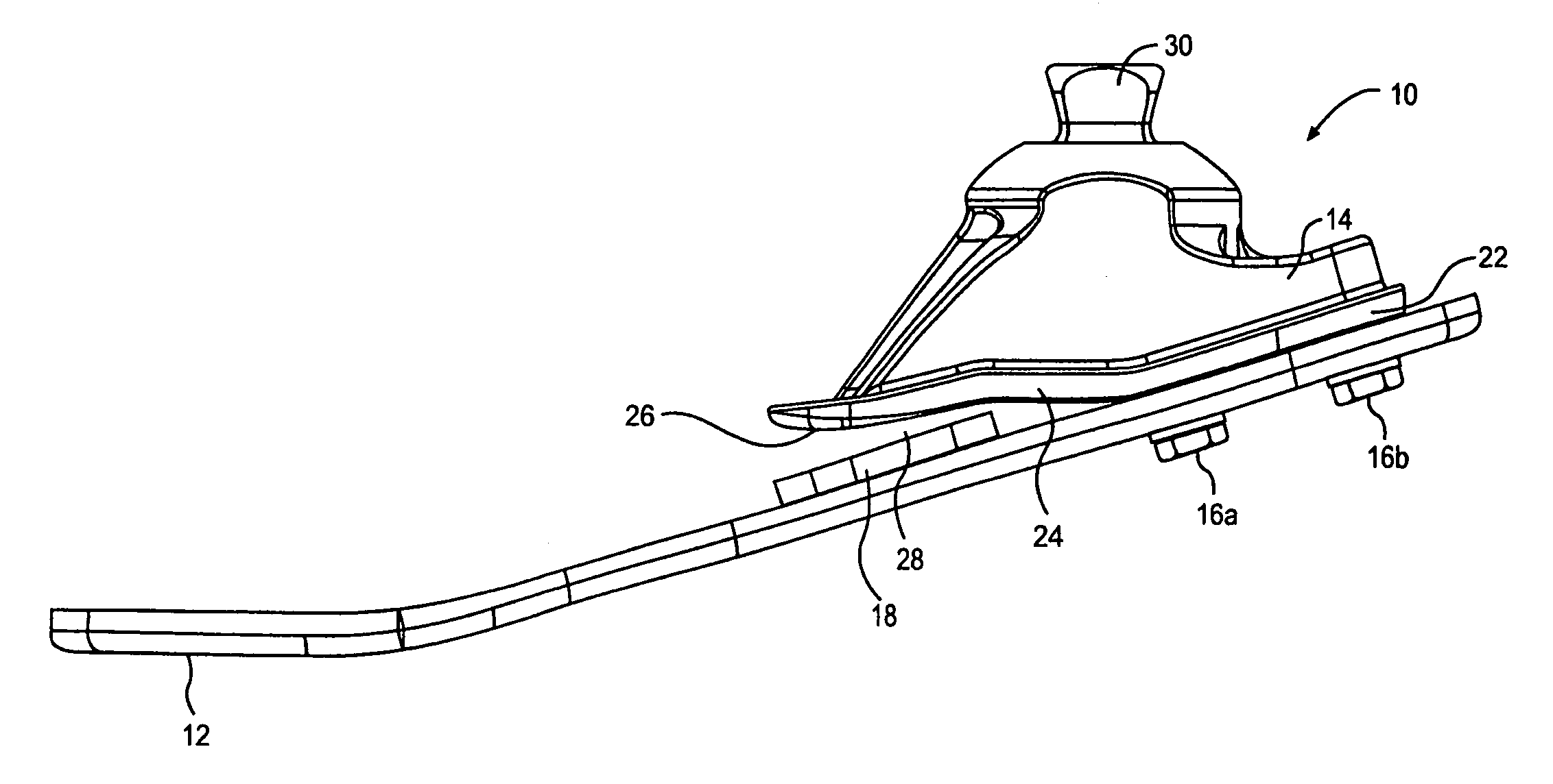
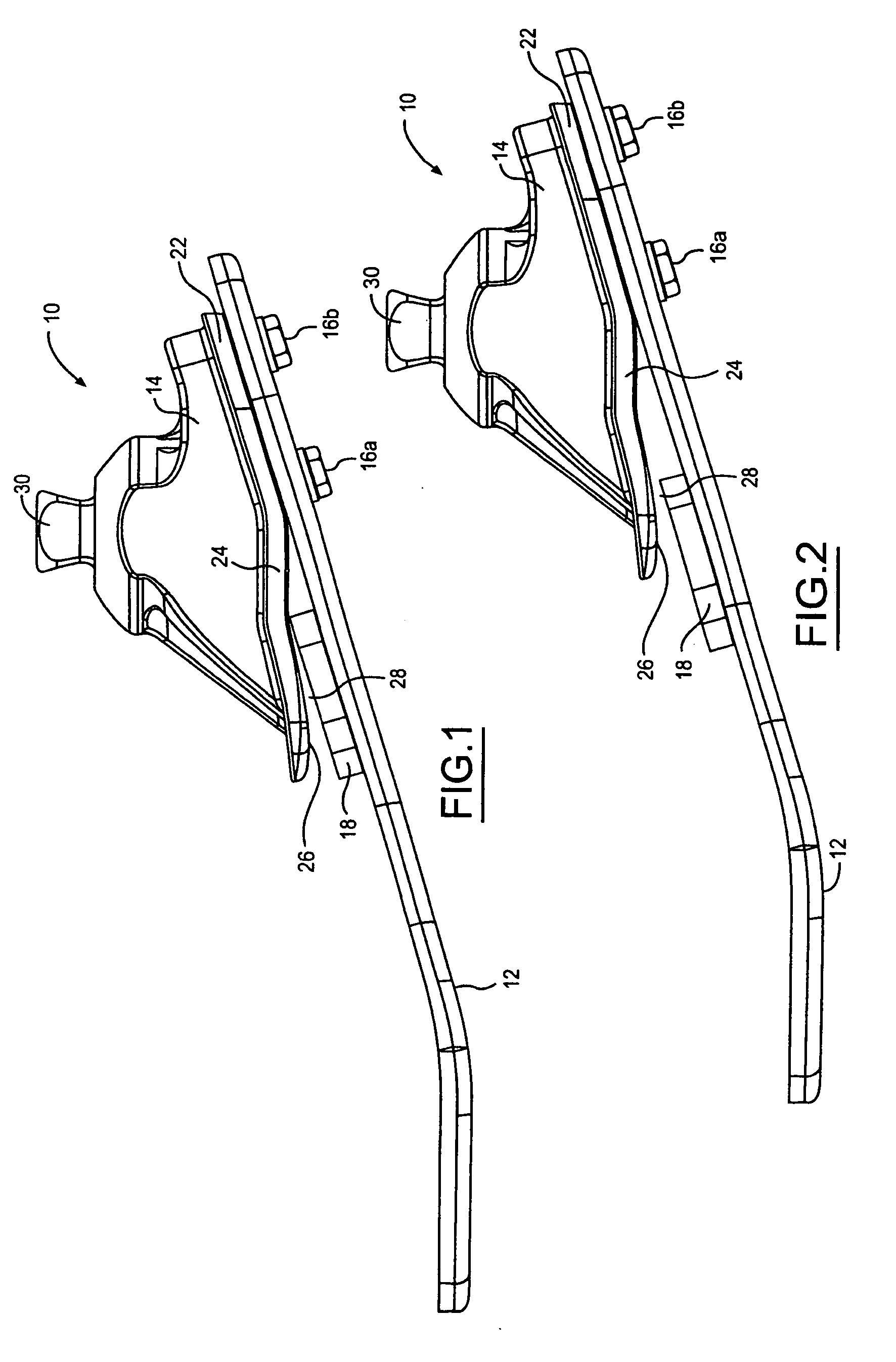
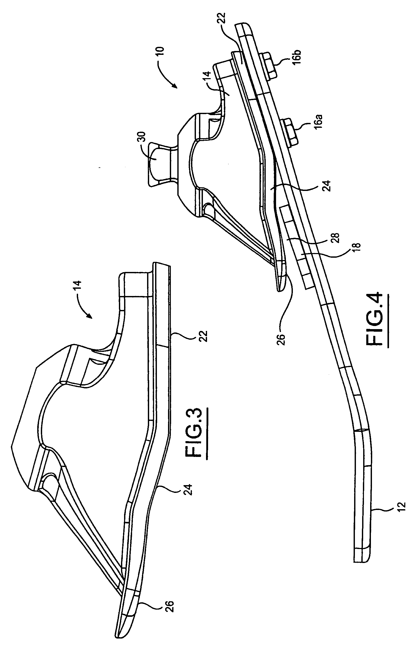
[0013] The present invention is directed to a prosthetic foot which is attachable to a leg prosthesis and which provides for a natural foot action. The prosthetic foot of the present invention includes a sole plate formed from a body of resilient material. The sole plate is elongated along an anterior and posterior axis, and the anterior portion of the sole plate defines the toe portion of the prosthetic foot and the posterior portion defines the heel portion of the prosthetic foot. An ankle member includes a planar portion that is rigidly affixed to the sole plate at the heel portion. The ankle member also includes an extension portion which is anterior of the planar portion. When the ankle member is affixed to the sole plate, the extension portion is spaced apart from the surface of the sole plate. The prosthetic foot also includes a resilient pad which is disposed in the space between the extension portion of the ankle member and the sole plate.

[0014] Referring now to FIG. 1, th...


PUM


Abstract

A prosthetic foot includes a sole plate having a body formed of resilient material. The sole plate is elongated along an anterior and posterior axis wherein an anterior portion of the plate defines a toe portion and the posterior portion defines a heel portion. An ankle member having a planar portion in contact with the sole plate is rigidly affixed to the sole plate at the heel portion. The ankle member has an extension portion positioned anterior of the planar portion and separated from the planar portion by a transition portion. A resilient pad is disposed between the contact portion of the ankle member and the sole plate. The resilient pad and extension portion of ankle member define a gap such that as a user's weight is transferred anterior following initial contact, the extension portion of the ankle member tilts forward reducing the gap formed between the resilient pad and the extension portion for improving the dorsiflexion of the prosthetic foot.

Description

RELATED APPLICATION [0001] This application claims priority of U.S. Provisional Patent Application Ser. No. 60 / 646,670 filed Jan. 25, 2005, which is incorporated herein by reference.FIELD OF THE INVENTION [0002] This invention relates generally to foot prostheses. More specifically, the invention relates to sub-malleolar, non-articulating foot prostheses. BACKGROUND OF THE INVENTION [0003] A prosthetic foot is a very important component of leg prostheses. A prosthetic foot must reliably store and release energy while flexing in a number of degrees of motion so as to properly coordinate with the muscular action when a user is walking, running or standing in place. In addition, a prosthetic foot must provide a reliable action over a large number of operational cycles under ambient conditions which include exposure to dust, dirt, various liquids and a large range of operational temperatures. In addition, it is generally desirable that a prosthetic foot be relatively low in cost and eas...

Claims


Application Information

Patent Timeline
Patent Type & Authority Applications(United States)
IPC IPC(8): A61F2/66
CPCA61F2/66A61F2/6607A61F2002/30359A61F2002/3051A61F2002/5003A61F2002/5007A61F2002/5055A61F2002/6621A61F2002/665A61F2220/0025A61F2220/0033A61F2002/30507
Inventor JOHNSON, CHRISTOPHER L.TASZREAK, AARON
Owner COLLEGE PARK IND INC
Why Eureka
Try Eureka