Air-conditioning installation, especially for motor vehicles

Inactive Publication Date: 2006-08-03
DAIMLER AG
View PDF4 Cites 15 Cited by
  • Summary
  • Abstract
  • Description
  • Claims
  • Application Information

AI Technical Summary

Benefits of technology

[0017] This minimizes the increase in pressure in the closed stationary air-conditioning circuit, since when the refrigerant is circulating in the stationary air-conditioning circuit a pressure increase occurs in the installation as soon as the liquid refrigerant enters the evaporator and is partially or completely evaporated therein. This increase in volume can lead to an increase in pressure in the installation. It is known that the refrigerant pressure level determines the evaporation temperature, and the higher this pressure level, the higher also is the evaporation temperature.
[0018] Furthermore, this position of the refrigerant collector ensures that t

Problems solved by technology

Evaporator and refrigeration accumulator are connected in parallel on the refrigerant side, which leads to high levels of outlay on connections and components and therefore disadvantageously to high manufacturing costs.
Furthermore, an installation of this type of course also takes up valuable space in a motor vehicle, in particular in a passenger automobile.
This is a practice which is a considerable burden on the environment, on account of pollutant and noise emissions, and in addition consumes fuel.
Consequently, the refrigeration installation likewise stops, and consequently it is impossible for functions which are of relevance to safety and comfort, such as cooling and drying of the incoming air for the passenger compartment, to be performed.
The current concepts are as yet unsuitable for use in passenger automobiles, on account of the ratios of performance to space and weig

Method used


Image

  • Air-conditioning installation, especially for motor vehicles
  • Air-conditioning installation, especially for motor vehicles
  • Air-conditioning installation, especially for motor vehicles

Examples


Embodiment Construction

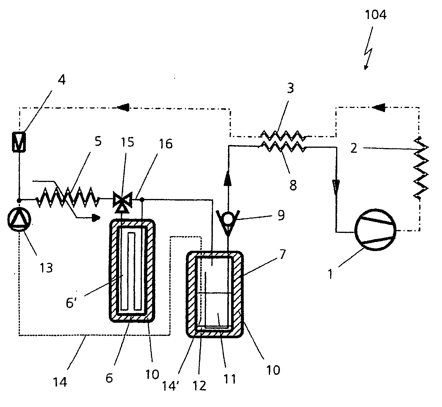
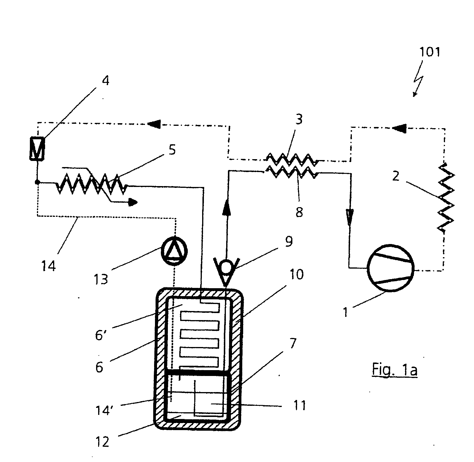
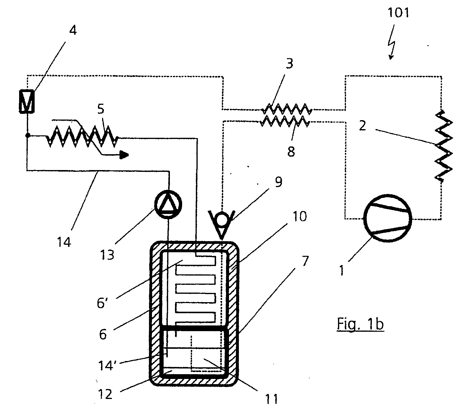
[0031]FIG. 1a illustrates an air-conditioning installation, which is denoted overall by reference numeral 101, in AC operation. When the compression circuit is running (high-pressure region indicated by dot-dashed lines and suction region indicated by continuous lines), a refrigerant 11 is brought to a high temperature and pressure level in a compressor 1, is cooled in the ambient heat exchanger 2 before being cooled further via an internal heat exchanger 3. It then passes through an expansion valve 4 and is expanded to a lower pressure and temperature level (10° C. to 0° C., depending on the temperature requirements). In an evaporator 5, the refrigerant 11 takes up energy from the useful air which is passed to the interior (passenger compartment—not shown), cools and dries this air and is in the process partially or completely evaporated before it passes to a thermal accumulator 6. In the present exemplary embodiment, the thermal accumulator 6 is located downstream of the evaporato...


PUM


Abstract

The invention relates to an air-conditioning installation, in particular for motor vehicles, having a compression refrigeration circuit of a refrigerant for A/C operation with a high-pressure region, a suction region and a connected stationary air-conditioning circuit, in particular for stationary air-conditioning operation when the compression refrigeration circuit is switched off, having a compressor, an expansion valve, an evaporator as cooler for releasing refrigeration to the environment, and a thermal accumulator comprising a heat storage medium. The thermal accumulator serves as a refrigeration accumulator and as a condenser during stationary air-conditioning operation. The refrigerant which is present serves as heat transfer medium for transferring the refrigeration from the thermal accumulator to the evaporator in the stationary air-conditioning circuit. The evaporator and the thermal accumulator are connected in series in terms of the flow of refrigerant.

Description

BACKGROUND OF THE INVENTION [0001] 1. Field of the Invention [0002] The invention relates to an air-conditioning installation, in particular for motor vehicles in accordance with the preamble of claim 1. [0003] 2. Related Art of the Invention [0004] An air-conditioning installation of the generic type is known from DE 37 04 182 A1. In that installation, a cooling installation is operated in combination with a refrigeration accumulator, with the refrigerant being used as heat-transfer medium to transfer the refrigeration from the refrigeration accumulator to the evaporator with the aid of a circulation pump. Evaporator and refrigeration accumulator are connected in parallel on the refrigerant side, which leads to high levels of outlay on connections and components and therefore disadvantageously to high manufacturing costs. Furthermore, an installation of this type of course also takes up valuable space in a motor vehicle, in particular in a passenger automobile. [0005] Conventional ...

Claims


Application Information

Patent Timeline
IPC IPC(8): F25D17/02B60H1/32B60H1/00F25B5/04F25B9/00F25B40/00F25D16/00
CPCB60H1/005F25B5/04F25B9/008F25B40/00F25B2309/061F25B2400/24F25B2500/01F25D16/00F28D20/021Y02E60/14F25B2309/06
Inventor HARM, KLAUS
Owner DAIMLER AG
Why Eureka
Try Eureka