Ventilation mask

a mask and air vent technology, applied in the field of ventilation masks, can solve the problems of patient's head and relatively large expiratory noise, and achieve the effect of low sound emission during expiration and high level of wearing comfor

Inactive Publication Date: 2006-08-03
WEINMANN GERATE FUR MEDIZIN
View PDF5 Cites 89 Cited by
  • Summary
  • Abstract
  • Description
  • Claims
  • Application Information

AI Technical Summary

Benefits of technology

[0009] The object of the present invention is to construct a ventilation mask of the aforementioned type in such a way that sound emission during expiration is low, a small number of parts are used, and a high level of wearing comfort is achieved.
[0011] Locating the outflow channel in the transition zone between the base of the mask and the contour element helps to provide an outflow channel with a relatively elongated shape, so that low flow velocities of the gas and thus low sound emissions are promoted. Furthermore, this location of the outflow channel makes it possible to dimension the outflow channel relatively narrowly to promote a diffuse outflow of the respiratory gas. Due to the elongated dimensioning of the outflow channel, its narrow dimensioning does not lead to an unfavorable increase in flow resistance, but rather a sufficiently large outflow area is provided.
[0012] The arrangement of the outflow channels in the transition zone between the base of the mask and the contour element also supports favorable manufacture of the parts from the standpoint of tool technology. Furthermore, it provides a very high degree of functionality and effective washing out of carbon dioxide, since the outflow channel is positioned relatively close to the patient's nose.
[0013] To prevent closure of the outflow channel by deformations of the structural members bordering the outflow channel, it is proposed that the outflow channel be divided by at least one spacing element.
[0024] Injection of the spacing ring on the contour element is an especially helpful way to contribute to simpler handling.

Problems solved by technology

However, this produces relatively large expiratory noises directly in the area of the patient's head.
This is unacceptable, especially if the mask is to be used during the night.

Method used


Image

  • Ventilation mask
  • Ventilation mask
  • Ventilation mask

Examples


Embodiment Construction

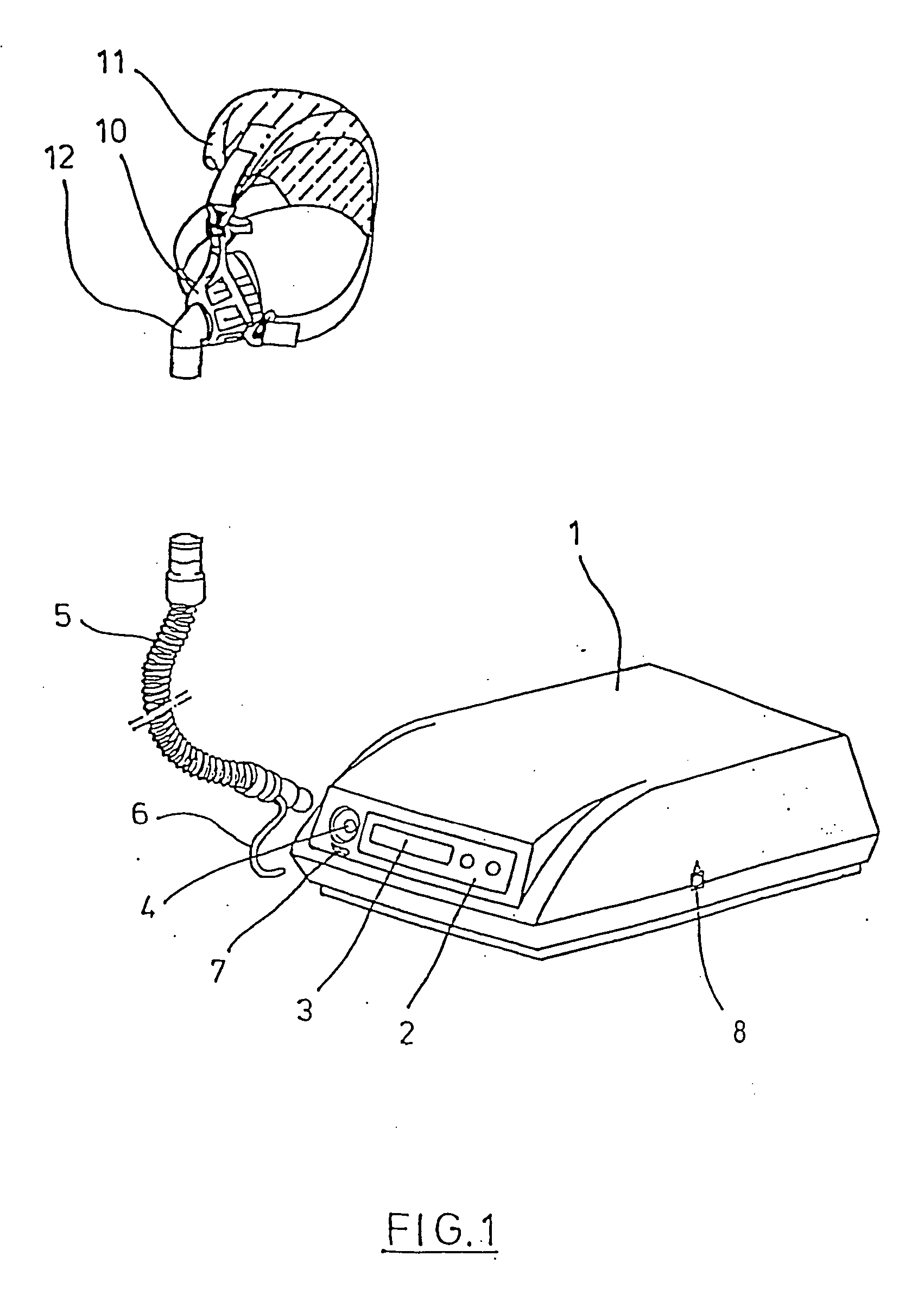
[0036]FIG. 1 shows the basic construction of a ventilation device. In the area of the unit housing 1, which has an operating panel 2 and a display 3, a respiratory gas pump is installed in an internal space in the unit. The connecting hose 5 is attached by a coupling 4. An additional pressure-measuring hose 6, which can be connected with the unit housing 1 by a pressure input connection 7, can run along the connecting hose 5. To allow data transmission, the unit housing 1 has an interface 8.

[0037]FIG. 1 also shows a ventilation mask 10, which is designed as a nasal mask. The mask can be fastened on the head of a patient by a head fastening device 11. A coupling element 12 is provided in the expanded region of the ventilation mask 10 that faces the connecting hose 5.

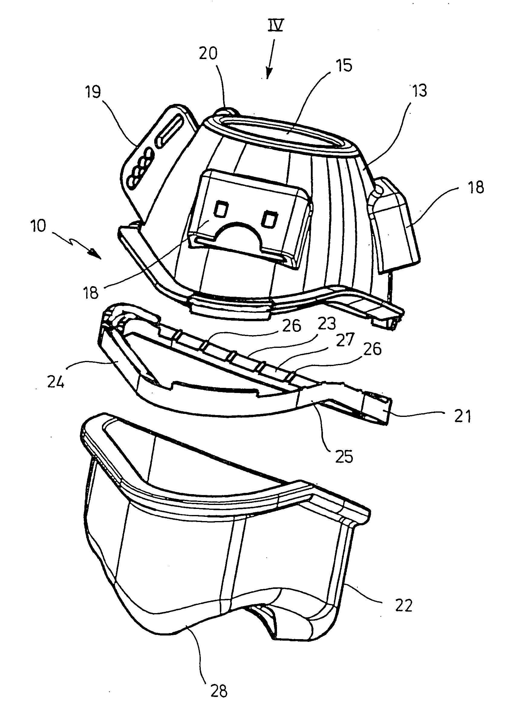
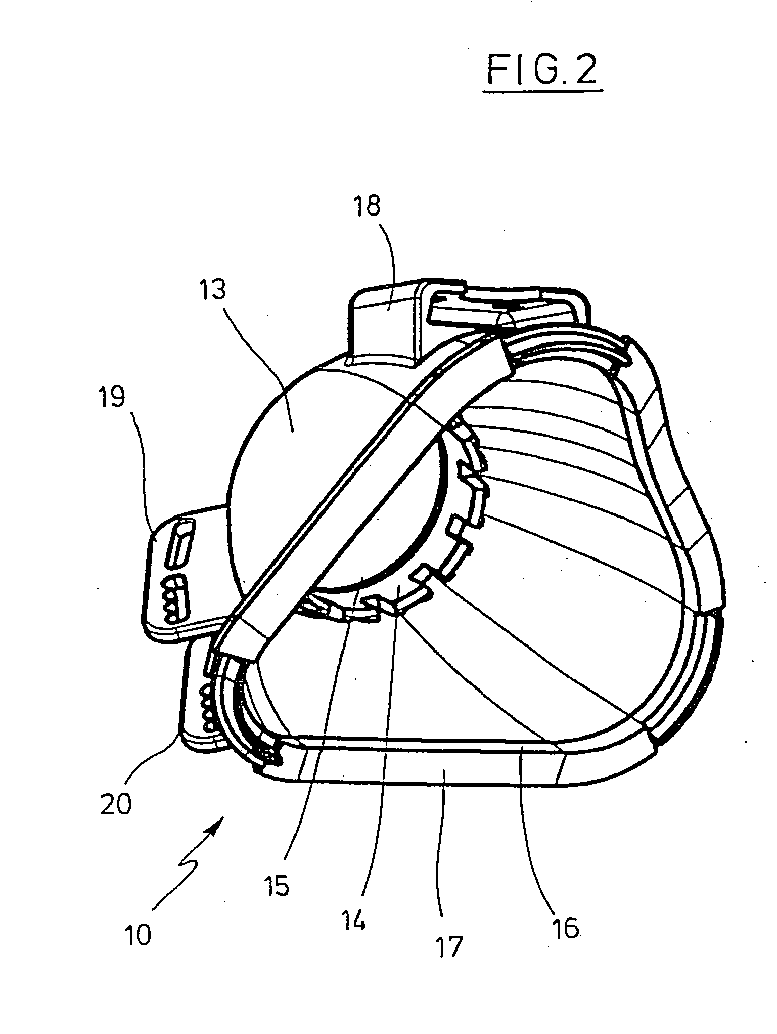
[0038]FIG. 2 shows a perspective view of the base 13 of the ventilation mask 10. The base 13 of the mask has a mounting component 14 for the coupling element 12. In the embodiment shown in FIG. 2, the mounting component...


PUM

PropertyMeasurementUnit
pressureaaaaaaaaaa
pressureaaaaaaaaaa
pressureaaaaaaaaaa

Abstract

A ventilation mask used for the ventilation of a patient has a mask base and a contour element that fits on the patient's face. At least one outflow channel for respiratory gas is provided in a transition zone between the base of the mask and the contour element. The outflow channel is bounded at least over portions thereof by a spacing ring arranged between the mask base and the contour element.

Description

CROSS-REFERENCE TO RELATED APPLICATIONS [0001] This application is a Continuation-in-Part Application of U.S. application Ser. No. 10 / 966,062.BACKGROUND OF THE INVENTION [0002] 1. Field of the Invention [0003] The present invention relates to a ventilation mask for the ventilation of a patient, which has a mask base and a contour element that fits on the patient's face. [0004] 2. Description of the Related Art [0005] A ventilation mask with a separate expiratory constituent is described, for example in DE-OS 199 03 732. The base of the mask is rigidly connected into a coupling element, which can be coupled with the expiratory constituent. The expiratory constituent can be fitted with a hose adapter, which connects the breathing mask to a ventilation unit via a ventilation hose. A ventilation mask of this type is suitable especially for use in CPAP therapy. [0006] Another ventilation mask is described in DE-OS 101 58 066. A ventilation hose is connected with the ventilation mask by a...

Claims


Application Information

Patent Timeline
Patent Type & Authority Applications(United States)
IPC IPC(8): A62B18/02A61M16/06B41J11/00B41M7/00C09D11/00
CPCA61M16/06B41J11/002B41M7/00C09D11/38A61M16/0858A61M16/0633
Inventor EIFLER, MARTINSCHULZ, GERD
Owner WEINMANN GERATE FUR MEDIZIN
Why Eureka
Try Eureka