Vehicle tire changer with integrated detector for tire pressure sensors

Active Publication Date: 2006-08-03
HUNTER ENG
View PDF15 Cites 10 Cited by
  • Summary
  • Abstract
  • Description
  • Claims
  • Application Information

AI Technical Summary

Benefits of technology

[0020]FIG. 2 is a perspective partial sectional view of a prior art tire pressure se

Problems solved by technology

However, indirect tire pressure monitoring systems cannot identify small changes in tire pressures, and are incapable of identifying situations in which all of the vehicle wheels are under-inflated.
Manual systems often require the operator to retrain or reposition the tire pressure sensors following a vehicle wheel rotation or service, a time-consuming and error-prone procedure.
If a tire pressure sensor associated with a tire pressure monitoring system is installed about the wheel rim, w

Method used


Image

  • Vehicle tire changer with integrated detector for tire pressure sensors
  • Vehicle tire changer with integrated detector for tire pressure sensors
  • Vehicle tire changer with integrated detector for tire pressure sensors

Examples


Embodiment Construction

[0026] The following detailed description illustrates the invention by way of example and not by way of limitation. The description clearly enables one skilled in the art to make and use the invention, describes several embodiments, adaptations, variations, alternatives, and uses of the invention, including what is presently believed to be the best mode of carrying out the invention.

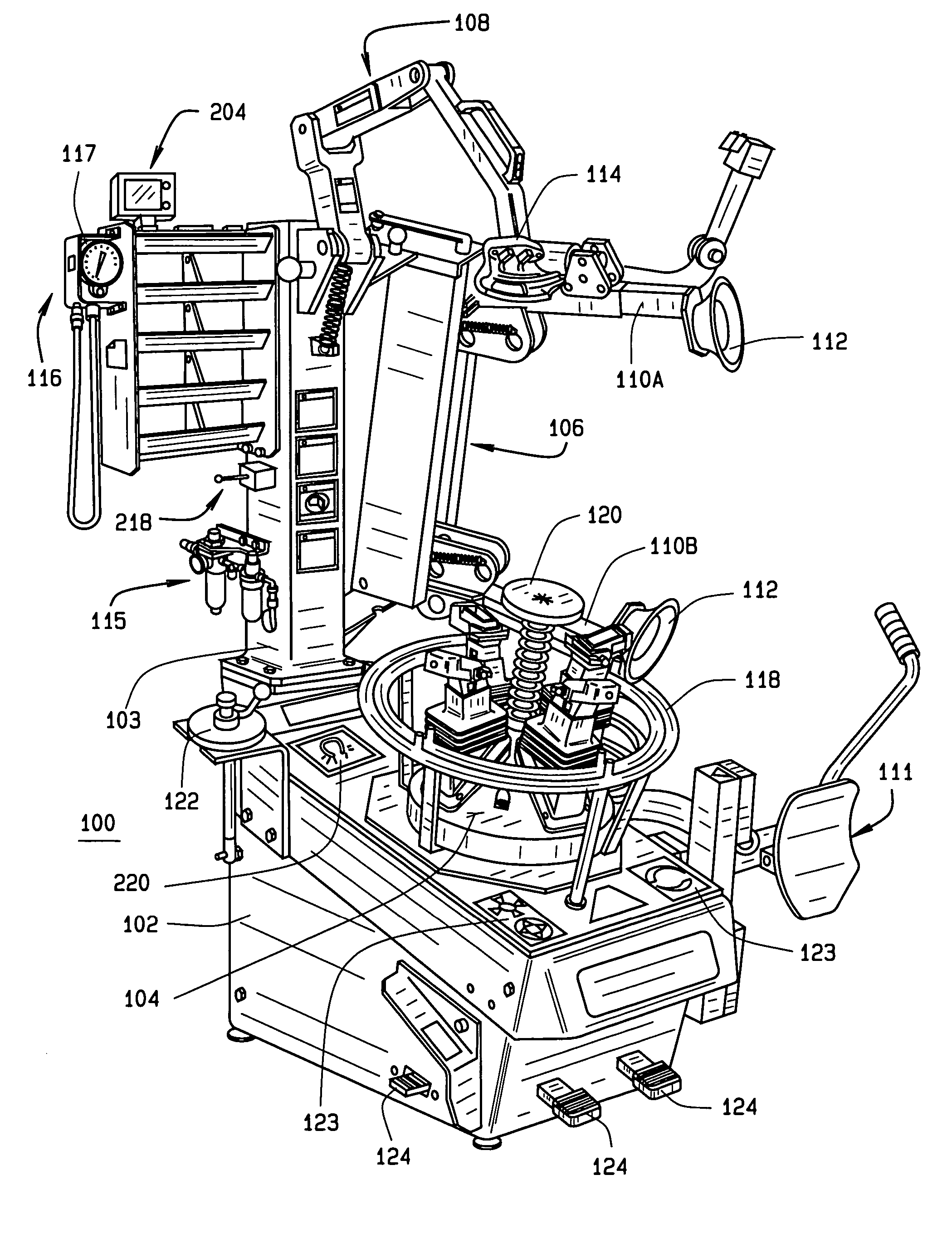
[0027] Turning to FIG. 4, a vehicle wheel tire changing system embodiment of the present invention is shown generally at 100. The vehicle wheel tire changing system 100 is shown configured with standard attachments for the mounting and dismounting of tires from wheel rims, however, it will be recognize that the vehicle wheel tire changing system 100 may be configured only to alter the mounting of a tire about a vehicle wheel rim, and not for removal or installation of a tire thereon. The vehicle wheel tire changing system 100 in one embodiment consists of a base 102 which supports a wheel assembly clamp...


PUM


Abstract

An improved vehicle wheel tire changing system configured to detect the presence of a tire pressure monitoring system sensor, mounted within a vehicle wheel assembly, prior to altering the mounting of a tire on an associated wheel rim.

Description

CROSS-REFERENCE TO RELATED APPLICATIONS [0001] Not Applicable. STATEMENT REGARDING FEDERALLY SPONSORED RESEARCH [0002] Not Applicable. BACKGROUND OF THE INVENTION [0003] The present invention is related generally to vehicle wheel tire changing systems, and in particular, to an improved vehicle wheel tire changing system configured to detect the presence of a tire pressure monitoring system sensor mounted within a vehicle wheel assembly prior to altering the mounting of a tire on an associated wheel rim. [0004] Modern vehicle wheel assemblies on most motor vehicles today consist of a pneumatic tire mounted or seated on a wheel rim, such as shown in FIG. 1. The tire is secured to the wheel rim by forces exerted between the inner peripheral edges of the tire, i.e. the beads, and the mating surfaces of the wheel rim, i.e. the bead seats. Pressurized air contained within the toroidal volume defined between the tire and wheel rim supports the tire against the weight of the vehicle. Tire p...

Claims


Application Information

Patent Timeline
IPC IPC(8): B60C25/00
CPCB60C25/138
Inventor HILLMAN, SCOTTSTREGE, TIMOTHY A.
Owner HUNTER ENG
Why Eureka
Try Eureka