Multi-ply collapsible bulk container

a multi-ply, bulk container technology, applied in the field of bulk containers, can solve the problems of affecting the appearance of the container at these folds, affecting and reducing the strength of the erected container, so as to maintain the structural integrity of the container

Inactive Publication Date: 2006-08-03
MENASHA
View PDF25 Cites 27 Cited by
  • Summary
  • Abstract
  • Description
  • Claims
  • Application Information

AI Technical Summary

Benefits of technology

[0006] In one embodiment, the walls of the container are formed of at least two three-ply corrugated cardboard blanks and at least two two-ply corrugated cardboard inserts, wherein the inserts do not overlap each other. In another embodiment, the walls are formed of two additional three-ply corrugated cardboard blanks. In another embodiment, the walls are formed of at least eight-ply corrugated cardboard sheet. In another embodiment, a third inner corner and a fourth inner corner each have a score line allowing each of the third and fourth corners to fold at an angle of at least 90° while maintaining the structural integrity of the container.

Problems solved by technology

Along those portions of the bulk container which are to be folded to a 0° angle (often termed a reverse fold) in passing from the original, planar blank to the collapsed or knocked down tube, there is, in prior art bulk containers of this type, often significant damage to the structural integrity of the container.
The most common such damage is a distortion and tearing caused by compression and / or tension of the paperboard material at these vertically extending edges of the bulk container, where the 0° folds become 90° folds or edges upon refolding 90° attendant set-up or erection.
The strength of the erected container is diminished by this damage and the appearance of the container at these folds is also marred.
However, thicker walls experience greater stresses at the fold lines, particularly when folded to angles approaching 0°.
Scoring or crushing corners are known methods to ease the pressure created at a fold line, but prior scoring arrangements and methods have drawbacks.
Other designs do not fold tightly, leaving space on the inside of the collapsed container and, more importantly, creating bulges in the material near the reverse fold line.

Method used


Image

  • Multi-ply collapsible bulk container
  • Multi-ply collapsible bulk container
  • Multi-ply collapsible bulk container

Examples


Embodiment Construction

[0037] While this invention is susceptible of embodiments in many different forms, there are shown in the drawings and will herein be described in detail preferred embodiments of the invention with the understanding that the present disclosure is to be considered as an exemplification of the principles of the invention and is not intended to limit the broad aspect of the invention to the embodiments illustrated.

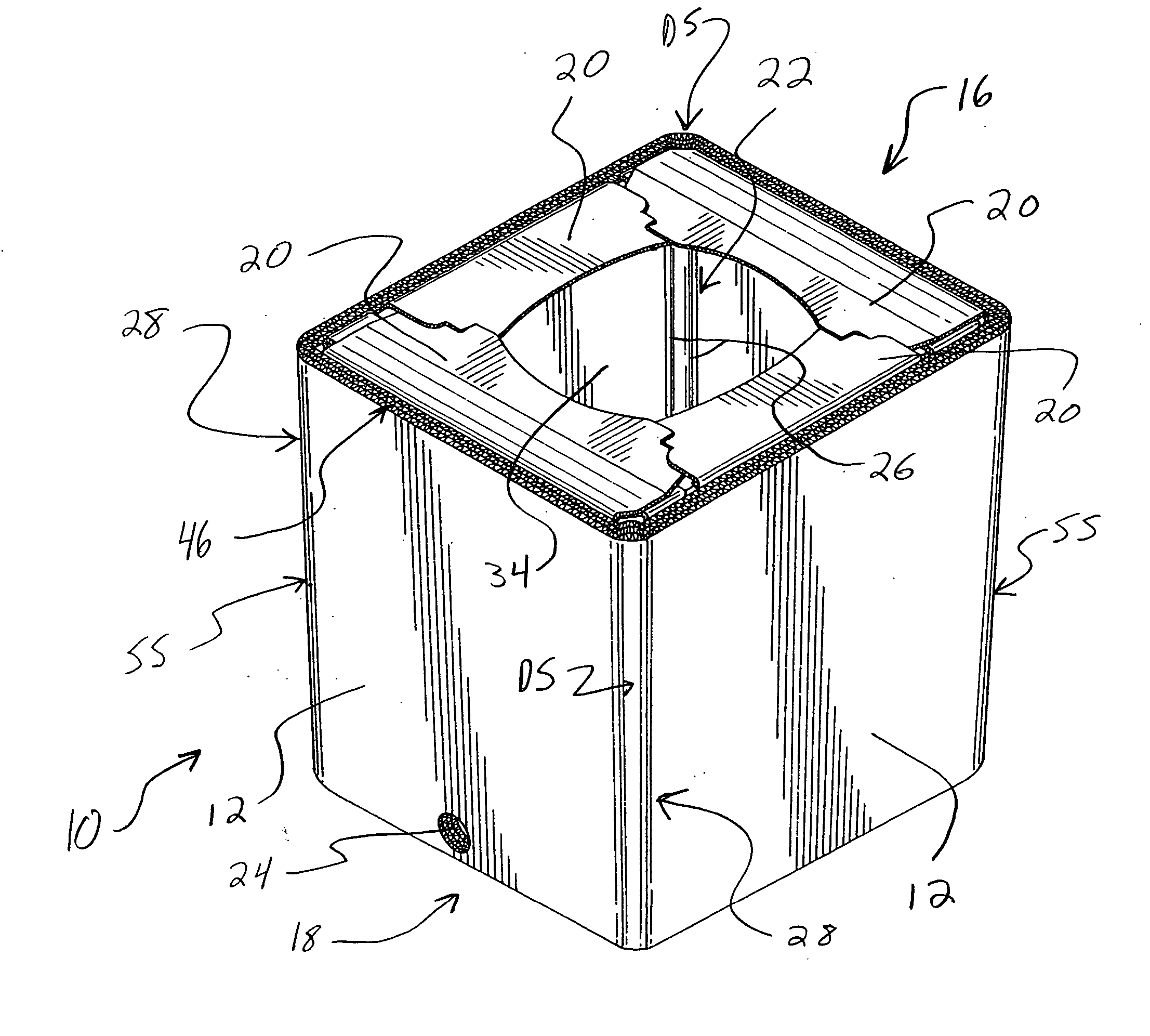
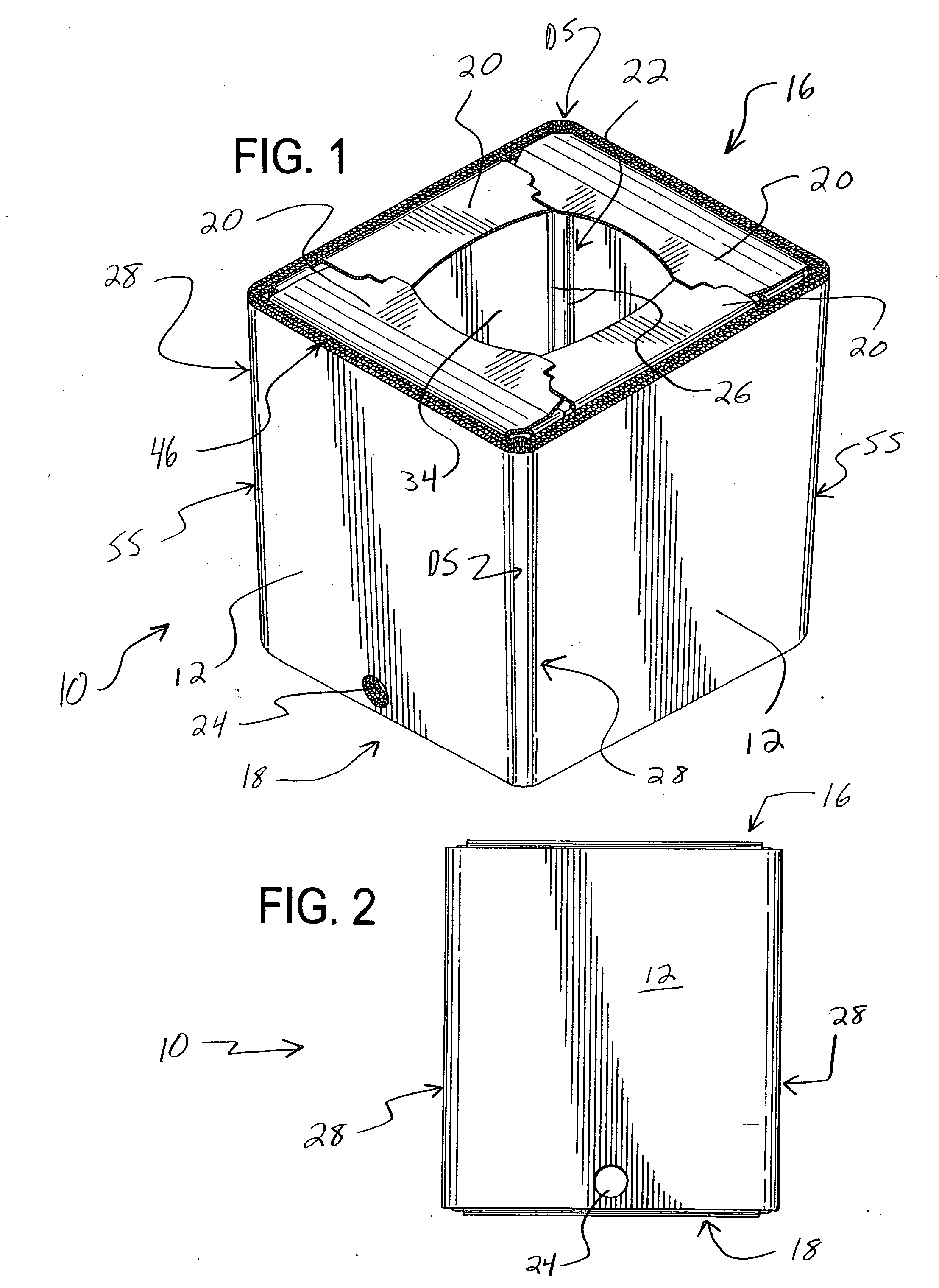
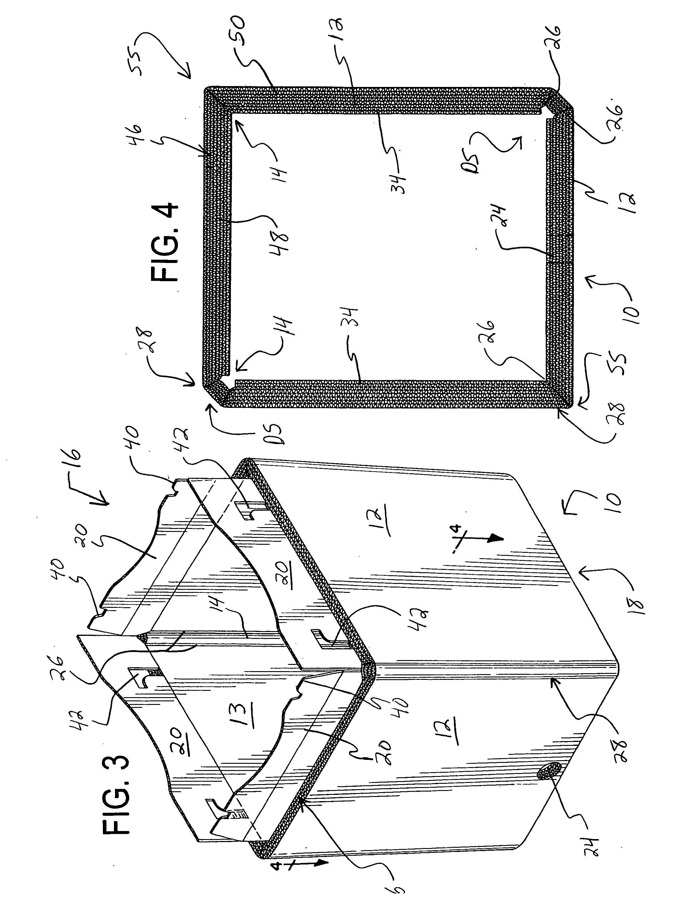
[0038] Referring now to FIGS. 1-21, and initially to FIGS. 1 and 14, there is shown a bulk container 10 having four substantially planar walls 12 and four corners 28, each corner 28 connecting two walls 12, a top 16 formed by four foldable flaps 20, and a bottom 18 formed by four foldable flaps 20. A preferred embodiment is depicted in FIGS. 1-13, and the most preferred embodiment is depicted in FIGS. 14-21. The walls 12 of the container 10 are formed of a sheet material, preferably cardboard. As shown in FIGS. 1 and 14, the container 10 is rectangular, having bi-lateral sym...


PUM


Abstract

A bulk container is disclosed, having a plurality of substantially planar walls, a plurality of corners connecting the walls, and a top and a bottom both formed by a plurality of foldable flaps. A first corner and a second corner opposite the first corner each have two substantially parallel score lines on an inner side of each corner allowing the corners to fold at an angle of substantially 0° while maintaining the structural integrity of the container. The walls of the container are constructed from a multi-ply corrugated cardboard sleeve made up of two layers of multi-ply corrugated cardboard laminated to each other. Two corrugated cardboard inserts, each having foldable top and bottom flaps are laminated to the sleeve. Also disclosed is a method of manufacturing the container using a number of blanks and inserts.

Description

TECHNICAL FIELD [0001] The invention relates generally to a bulk container, and more specifically to a collapsible cardboard container adapted to hold a flowable substance contained in a bag. BACKGROUND OF THE INVENTION [0002] Large bulk containers are often formed from a generally rectangular blank, usually flat, which has been suitably scored and crushed, by folding certain panels of the blank and then joining the ends of the blank to form a flattened tube structure. After the formation of the blank into a collapsed tube by joining its opposite ends, the packager or final user of the bulk container then unfolds or erects the flattened tube structure into its expanded, tubular condition or configuration, to thereby form a bulk container of generally rectangular configuration. Along those portions of the bulk container which are to be folded to a 0° angle (often termed a reverse fold) in passing from the original, planar blank to the collapsed or knocked down tube, there is, in prio...

Claims


Application Information

Patent Timeline
Patent Type & Authority Applications(United States)
IPC IPC(8): B65D3/22B65D5/10B65D5/56
CPCB65D5/10B65D5/4266B65D5/603
Inventor MCDOWELL, RICHARD B.
Owner MENASHA
Why Eureka
Try Eureka