Endoscope comprising a longitudinally guided everting tube

a technology of longitudinal guide and endoscope, which is applied in the direction of endoscope, stent, medical science, etc., can solve the problems of inability to examine patients, deterioration of drive power of drive means, and pain for patients to be examined, so as to reduce the friction between the two profiles

Inactive Publication Date: 2006-08-03
INVENDO MEDICAL GMBH
View PDF14 Cites 20 Cited by
  • Summary
  • Abstract
  • Description
  • Claims
  • Application Information

AI Technical Summary

Benefits of technology

[0019] A conception of the invention which is close to this basic idea consists in designing the everting tube with profiles forming undercuts extending in the longitudinal direction of the everting tube (for example in the manner of a dovetail guide). The endoscope shaft is designed to have corresponding profiles at least in sections which at least partially extend in the direction of movement of the everting tube and slidingly engage in the profiles at the everting tube. Both profiles engage in such manner that a tensile force can be exerted on the everting tube in the direction of the endoscope shaft and possibly in the longitudinal direction of the shaft so as to prevent the everting tube from lifting off or detaching from the surface of the endoscope shaft. What is decisive in this type of longitudinal guiding means therefore is to design the undercuts to be not transverse to the direction of movement of the everting tube, as provided in the prior art mentioned in the beginning by arranging a snap ring, but to provide the undercuts in the longitudinal direction of movement of the everting tube, similarly to a travel rail, whereby the entire holding surface by which the everting tube is held at the endoscope shaft is enlarged and, moreover, the sliding friction between the two profiles is reduced in the case of a relative movement between the everting tube and the endoscope shaft.

Problems solved by technology

This can be very painful to the patient to be examined.
However, the solution according to prior art is based on the problem that due to the use of such stops an increased friction occurs between the latter and the everting tube, whereby the drive power of the drive means is deteriorated.
Furthermore, it is not possible by the afore-described arrangement to move the endoscope shaft independently and relative to the everting tube, respectively.
All these measures entail the problem, however, that they reduce the flexibility of the entire endoscope and thereby increase the bending radius thereof which can be minimally obtained.
Although by the above-described configuration the everting tube can be prevented from forming scales, such a solution has the problem of a high friction between the snap ring and the everting tube, however, whereby the drive force to be applied to the everting tube increases.

Method used


Image

  • Endoscope comprising a longitudinally guided everting tube
  • Endoscope comprising a longitudinally guided everting tube
  • Endoscope comprising a longitudinally guided everting tube

Examples


first embodiment

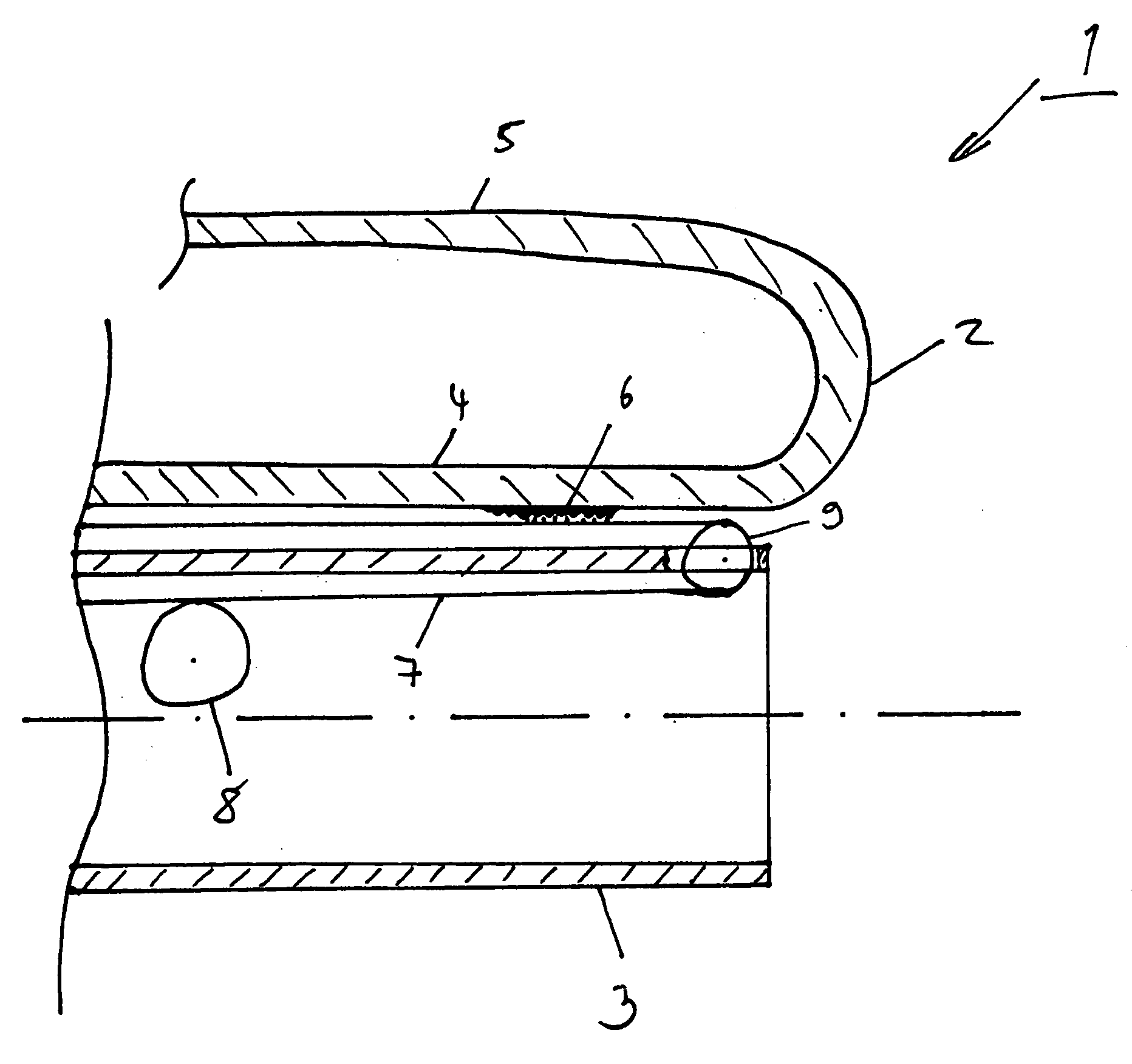
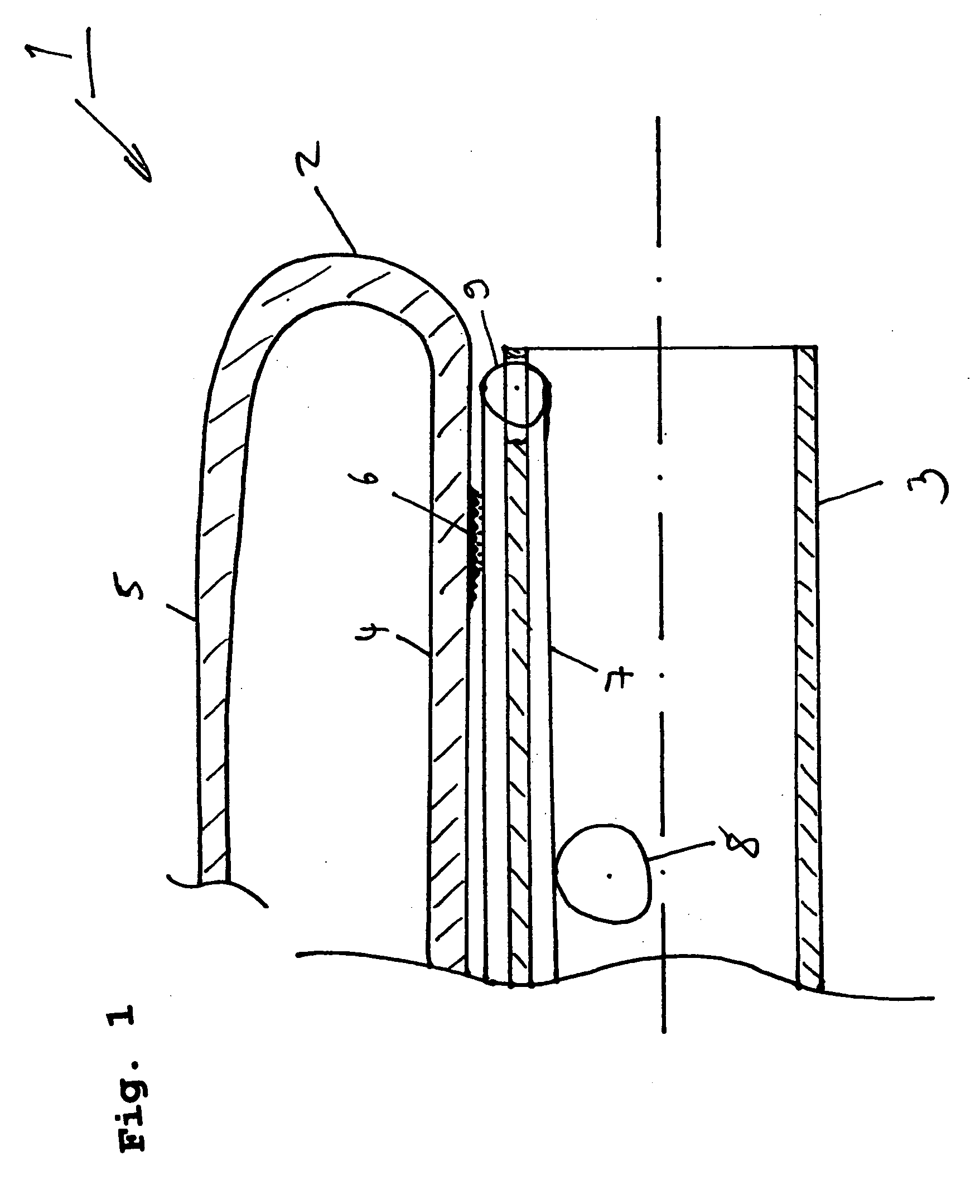
[0037] In accordance with the invention, between the radially inner portion 4 of the everting tube 2 and the endoscope shaft 3 there is an operative connection which is composed, on the one hand, of an engaging means 6 and, on the other hand, of a continuous conveyor 7 disposed at the endoscope shaft 3 which extends in the longitudinal direction of the endoscope shaft and acts as a longitudinal guiding means. The engaging means 6 consists of two meshing components disposed at the everting tube 3 and at the continuous conveyor 7, respectively. The component of the engaging means 6 disposed at the everting tube is arranged merely at one side of the everting tube, i.e. at the outside of the everting tube and extends at least in sections along the radially inner tube portion and also the radially outer tube portion, if necessary.

[0038] The engaging means 6 may have different embodiments, for instance a positive or a frictional embodiment or else a combined form of the two foregoing embo...

fourth embodiment

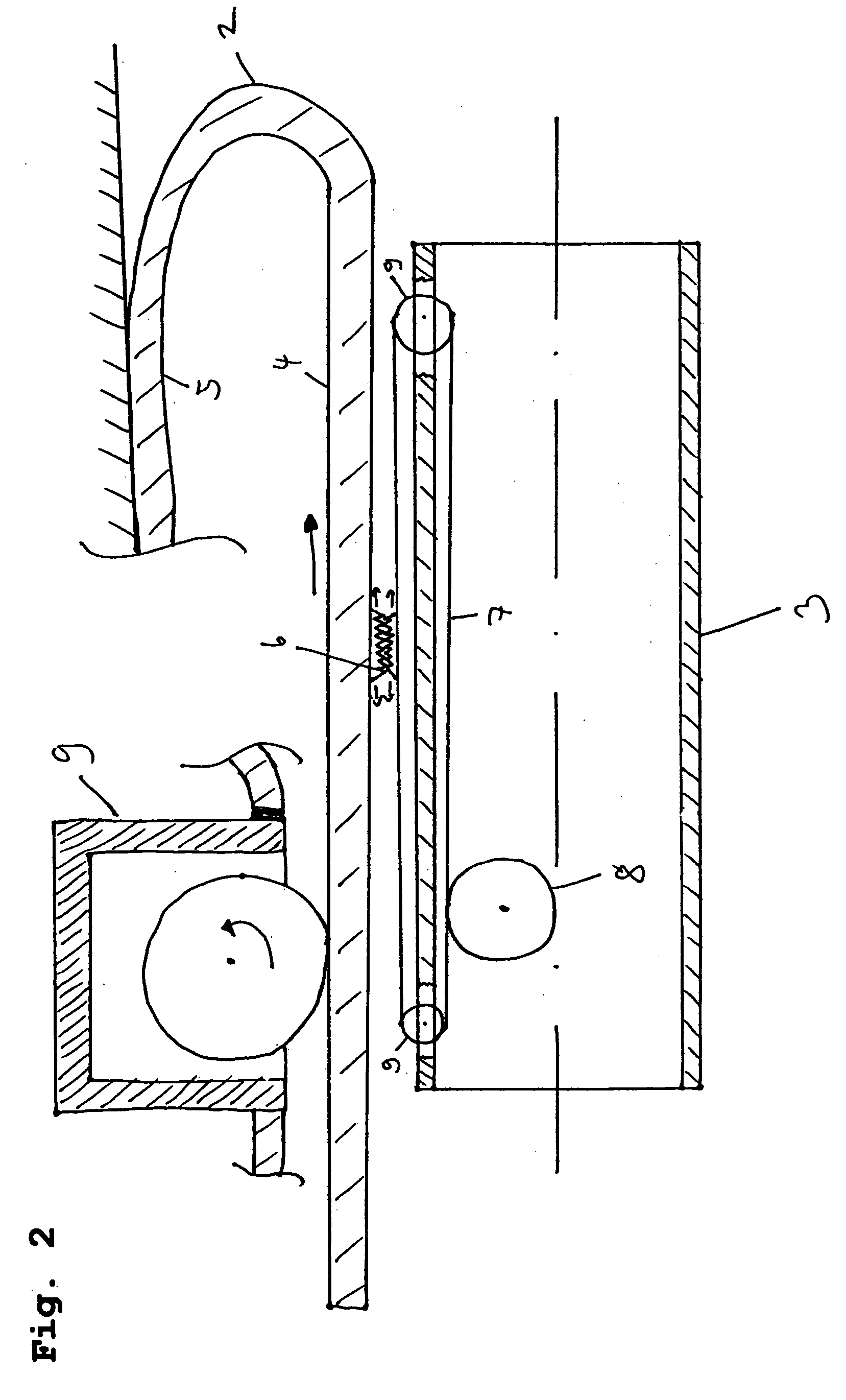
[0040] The continuous conveyor itself is disposed, as mentioned in the foregoing, at the endoscope shaft 3 and includes a radially inner portion and a radially outer portion. In this context, several arrangements of the continuous conveyor with respect to the everting tube are possible. The arrangement described in this embodiment describes a continuous conveyor which engages in the engaging means component disposed at the everting tube merely at a portion, namely the radially outer portion of the continuous conveyor. I.e. the continuous conveyor is provided at least with a portion between the endoscope shaft 3 and the everting tube 2, whereas in the fourth embodiment described hereinafter merely a portion of the continuous conveyor is disposed between the endoscope shaft 3 and the everting tube 2 and a further radially outer portion of the continuous conveyor is disposed at the radially outer side of the radially outer portion of the everting tube, i.e. the continuous conveyor surr...

second embodiment

[0055] Usually it is understood by this type of drive that merely the endoscope shaft is directly driven by a drive means. When applied to the now following second embodiment of the present invention, the endoscope shaft 3 shows a drive means (not shown in detail) which moves the same in the everting tube 2. Via the continuous conveyor 7 engaged with the everting tube through the engaging means 6 the movement of the endoscope shaft 3 is transmitted to the radially inner portion 4 of the everting tube 2 which thereby moves forward, as described in the foregoing, in the canal, for instance the intestines. As the endoscope shaft 3 moves forward more quickly than the everting tube 2, as described before, the endoscope shaft 3 is likewise equipped with the balancing means 8 which moves (drives) the continuous conveyor 7 in such manner that the everting tube 2 performs its quasi “unrolling movement” more quickly, i.e. moves more quickly in the direction of insertion of the endoscope shaft...


PUM


Abstract

The present invention deals with an endoscope comprising an everting tube including a radially outer portion and a radially inner portion. The everting tube surrounds at least partly an endoscope shaft. Longitudinal guiding means which are engaged with each other are formed at each of the endoscope shaft and the everting tube. One of the longitudinal guiding means can be designed such that it forms an undercut, whereas the other is correspondingly shaped so that both longitudinal guiding means are in sliding engagement with each other. Moreover, the longitudinal guiding means can be, on the one hand, in the form of a continuous conveyor disposed at the endoscope shaft and, on the other hand, in the form of an engaging means disposed at the everting tube, which are engaged with each other.

Description

BACKGROUND OF THE INVENTION [0001] 1. Field of the Invention [0002] The present invention relates to a design of an endoscope comprising an everting tube and an endoscope shaft each being provided with a longitudinal guiding means. The present invention especially relates to an endoscope comprising a guided everting tube which is made to slidingly engage with the endoscope shaft by the fact that one of the longitudinal guiding means forms an undercut which is in sliding mesh with the correspondingly shaped other longitudinal guiding means. Furthermore the present invention relates to an endoscope in which the longitudinal guiding means are designed as a continuous conveyor at the endoscope shaft and as an engaging means at the everting tube. [0003] 2. Discussion of the Prior Art [0004] Endoscopes are substantially used for visually examining the esophagus, the stomach, the intestines from the stomach or from the anus, the urethra as well as the bladder. For this purpose, the endosco...

Claims


Application Information

Patent Timeline
Patent Type & Authority Applications(United States)
IPC IPC(8): A61B17/08
CPCA61B1/00151A61B1/31A61M25/0119A61F2/966
Inventor BOB, KONSTANTIN
Owner INVENDO MEDICAL GMBH
Why Eureka
Try Eureka