Seal structure in hydraulic cylinder, and said hydraulic cylinder

a technology of sealing structure and hydraulic cylinder, which is applied in the direction of engine sealing, plunger, trunk piston, etc., can solve the problems of permanent deformation or adhesion of the packing to the slide-receiving face, damage or deterioration of the packing, and direct impact on the packing, so as to reduce the friction between the packing and the slide-receiving face, reduce the operating efficiency or togging, and smooth the piston operation

Inactive Publication Date: 2021-01-07
SMC CORP
View PDF0 Cites 0 Cited by
  • Summary
  • Abstract
  • Description
  • Claims
  • Application Information

AI Technical Summary

Benefits of technology

[0015]As described above, according to the present invention, the packing, which includes the first sealing part and the second sealing part, held in the recess groove has an outside diameter smaller than the inside diameter of the cylinder hole. However, while the compressed fluid is supplied to either one of the first chamber and the second chamber, the side edge of the packing that is adjacent to the chamber to which the compressed fluid is supplied, or a high-pressure chamber, is radially stretched by elastic deformation due to the pressure of the compressed fluid, thus causing the sealing part that is one of the first sealing part and the second sealing part and that is adjacent to the high-pressure chamber to reduce the gap formed with the slide-receiving face of the cylinder hole or come into contact with the slide-receiving face.
[0016]Therefore, even while the piston is maintained in a stopped state in the cylinder hole for a long time, for example, while the compressed fluid is supplied to neither the first chamber nor the second chamber, the sealing parts of the packing are not in contact with the slide-receiving face of the cylinder hole. Thus, the packing made of the rubber elastic material can be prevented from deteriorating, such as permanently deforming or adhering to the slide-receiving face of the cylinder hole. Furthermore, while the compressed fluid is supplied to either one of the first chamber and the second chamber, sliding friction between the packing and the slide-receiving face can be reduced as much as possible. This can reduce as much as possible the likelihood that conditions of the slide-receiving face (e.g., the roughness of the slide-receiving face and the state of a lubricating film) may cause an adverse effect on an operation of the piston (e.g., a reduction in operating efficiency or togging) and cause an adverse effect on the packing (e.g., damage to or deterioration of the packing resulting from sliding friction or torsion). This achieves smoother operation of the piston and allows longer service life of the packing.

Problems solved by technology

However, if the packing kept in pressure contact with the slide-receiving face of the cylinder hole is left for a long time without being moved, the packing may be permanently deformed or adhere to the slide-receiving face.
Furthermore, while the piston is being operated, the packing is directly affected by conditions of the slide-receiving face (e.g., the roughness of the slide-receiving face and the state of a lubricating film).
For example, sliding friction with the slide-receiving face or unevenness of the lubricating film may cause sliding friction or torsion of the packing and thus lead to damage to or deterioration of the packing or may cause an adverse effect on an operation of the piston (e.g., a reduction in operating efficiency or cogging).

Method used


Image

  • Seal structure in hydraulic cylinder, and said hydraulic cylinder
  • Seal structure in hydraulic cylinder, and said hydraulic cylinder
  • Seal structure in hydraulic cylinder, and said hydraulic cylinder

Examples


first embodiment

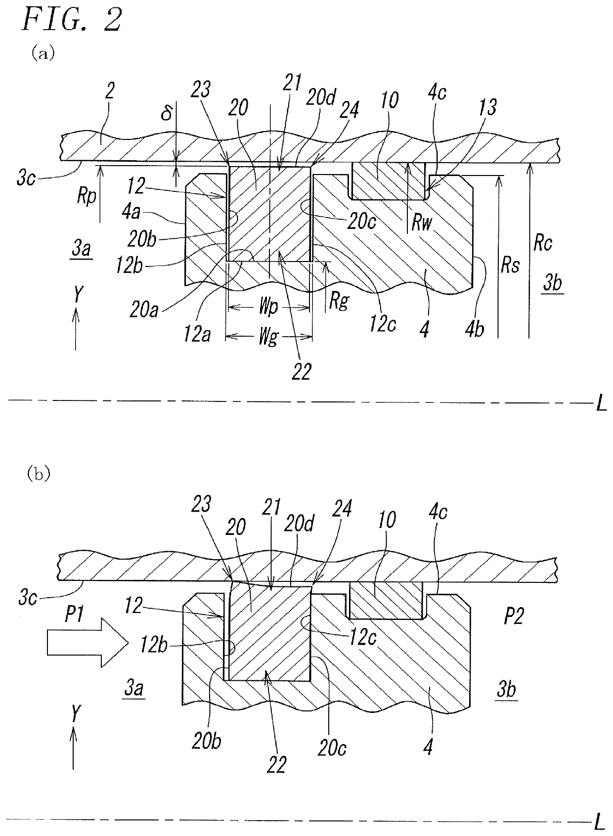
[0038]In the seal structure illustrated in FIG. 2, the packing 20 is solid and rectangular in cross-section along the axis L, and this rectangular shape is substantially symmetric with respect to the center line in the radial direction Y. Specifically, the outer shape of the packing 20 is defined by four faces, namely, the proximal face 20a that is the inner circumferential surface of the packing 20 and is circular about the axis L and extends flat along the axis L, a distal face 20d that is an outer circumferential surface of the packing 20 and is circular about the axis L and extends flat along the axis L, a first side face 20b that connects first ends of the proximal face 20a and the distal face 20d in the direction along the axis L, faces toward the first chamber 3a, and extends flat in the radial direction Y, and a second side face 20c that connects second ends of the proximal face 20a and the distal face 20d in the direction along the axis L, faces toward the second chamber 3...

second embodiment

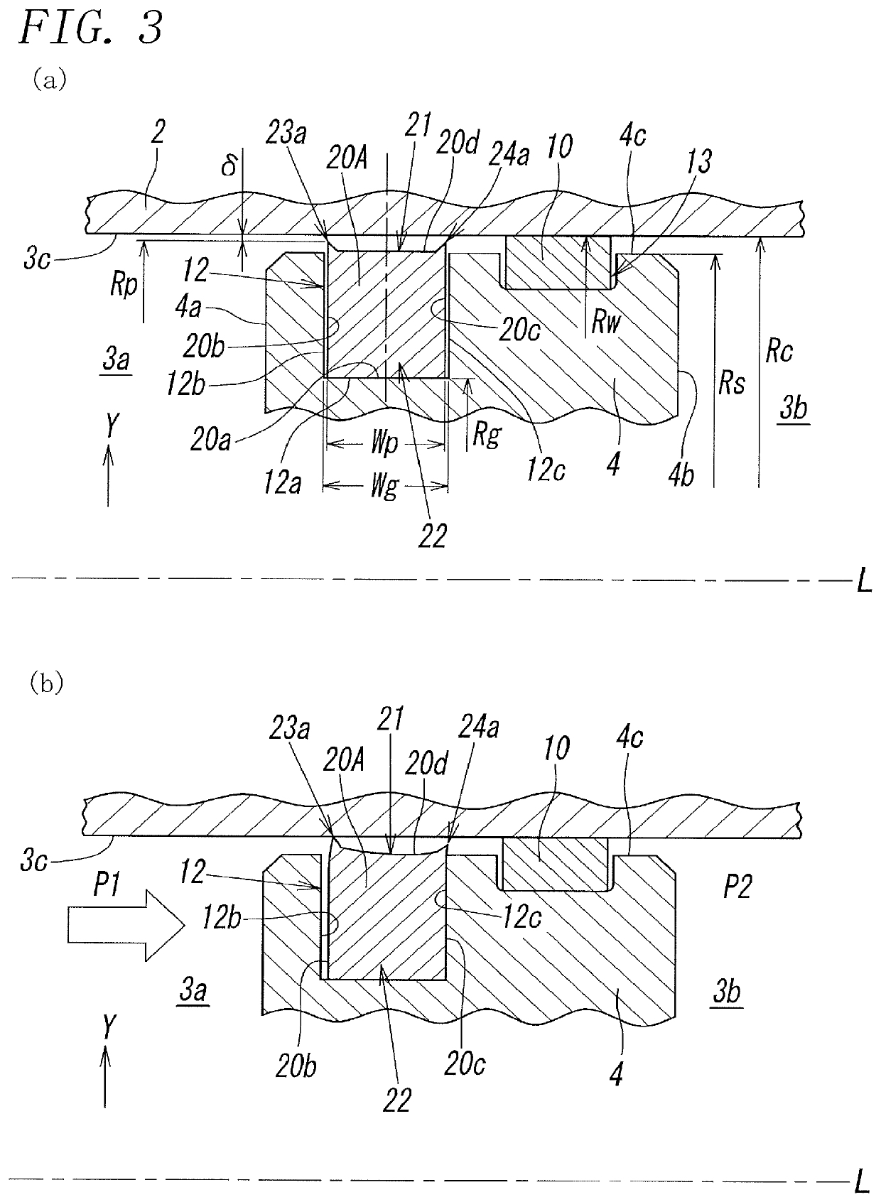
[0053]The cross-section of the packing 20A, which includes the first projection 23a and the second projection 24a, along the axis L is also symmetric with respect to the center line of the packing in the radial direction Y. Therefore, the distance from the distal face 20d to the tip of the projection 23a is equal to that to the tip of the projection 24a, and the distance from the slide-receiving face 3c of the cylinder hole 3 to the tip of the projection 23a is also equal to that to the tip of the projection 24a. The distance from the axis L to the tip of each of the projections 23a and 24a is the outside radius Rp of the packing 20A in the

[0054]Furthermore, in this packing 20A, each of the two projections 23a and 24a is wedge-shaped such that the width of the projection in the direction along the axis L gradually decreases in a direction from its proximal end on the distal face 20d to its distal end adjacent to the slide-receiving face 3c. Specifically, the first projection 23a is ...

third embodiment

[0057]As illustrated in FIG. 4(a), the seal structure includes a packing 20B, which has a circular first constriction groove 14a in the first side face 20b and a circular second constriction groove 14b in the second side face 20c such that these constriction grooves have the same radius from the axis L. The first and second constriction grooves 14a and 14b are intended to promote stretching of the above-described packing 20B in the radial direction Y when a fluid pressure in the chamber 3a or 3b acts on the side face 20b or 20c. In a cross-section of the packing 20B, the first and second constriction grooves 14a and 14b are opposite each other at the same level from the proximal face 20a to form a constriction 15 in which the width Wp of the packing is narrowed. In such arrangement, the cross-section of the packing 20B including the above-described two constriction grooves 14a and 14b is also symmetric with respect to its center line as in the other embodiments.

[0058]More specifica...


PUM


Abstract

A packing has an outer circumferential surface and includes a pair of sealing parts located at opposite ends of the packing in a direction along an axis. A piston has a sliding face having a first recess groove. When in the first recess groove, the packing has an outside diameter smaller than the diameter of a slide-receiving face of a cylinder hole. The piston divides the cylinder hole into a pair of chambers. While a compressed fluid is supplied to either one of the chambers, a side edge of the packing adjacent to the chamber at a high pressure is stretched in a radial direction by elastic deformation due to the pressure of the compressed fluid, thus causing a sealing part adjacent to the chamber at the high pressure to reduce a gap formed with the slide-receiving face of the cylinder hole or come into contact with the slide-receiving face.

Description

TECHNICAL FIELD[0001]The present invention relates to a seal structure in a hydraulic cylinder having a cylinder hole in which a piston is slidably disposed such that the seal structure is between a sliding face defined by an outer circumferential surface of the piston and a slide-receiving face defined by an inner circumferential surface of the cylinder hole, and relates to the hydraulic cylinder.BACKGROUND ART[0002]Hydraulic cylinders each having a cylinder hole in which a piston is slid by using the pressure of a compressed fluid, such as compressed air, have been widely known as disclosed in, for example, PTL 1. In such a hydraulic cylinder, the piston divides the cylinder hole into a pair of chambers. The piston has an outer circumferential surface, serving as a sliding face, around the axis thereof. The sliding face has thereon a sealing member made of a rubber elastic material, namely, an annular packing. Such arrangement prevents the compressed fluid from leaking from the pa...

Claims


Application Information

Patent Timeline
Patent Type & Authority Applications(United States)
IPC IPC(8): F15B15/14F16J15/48
CPCF15B15/1452F16J15/3268F16J15/48F16J15/18F16J15/3232F16J1/008F16J15/164F15B15/14F16J15/324F15B15/1428F16J15/3284F16J9/20
Inventor KUDO, MASAYUKITAKEDA, KENICHIKAWAKAMI, MASAHIKOTAMURA, KENODAKA, TSUKASA
Owner SMC CORP
Why Eureka
Try Eureka