Patient transfer and transport bed

a technology for transporting beds and patients, applied in nursing beds, medical science, ambulance services, etc., can solve problems such as inability to meet patient needs, process will continue to become more difficult and injury-prone, and hospital personnel, including nurses, will be injured

Inactive Publication Date: 2006-08-10
DANE INDS
View PDF26 Cites 21 Cited by
  • Summary
  • Abstract
  • Description
  • Claims
  • Application Information

AI Technical Summary

Benefits of technology

[0008] The present invention, in another embodiment, is a method for transferring a patient from a bed to a transfer and transport device. In this embodiment, the method includes positioning the transfer and transport device along side the bed. The height of the transfer platform is manipulated such that the support arms are above the bed height. The wheels of the device are locked to prevent movement during the transfer process. The transfer arms are extended until they extend to near a center

Problems solved by technology

Often the patient requiring movement is not conscious or cannot physically assist in the transfer, and so must be transferred by hospital personnel.
This process is a leading cause of injuries to hospital personnel, including nurses.
Furthermore, this process can lead to injury to the patient caused either by improper manipulation or dropping.
This process will continue to become more difficult and injury-prone in the future, as studie

Method used


Image

  • Patient transfer and transport bed
  • Patient transfer and transport bed
  • Patient transfer and transport bed

Examples


Embodiment Construction

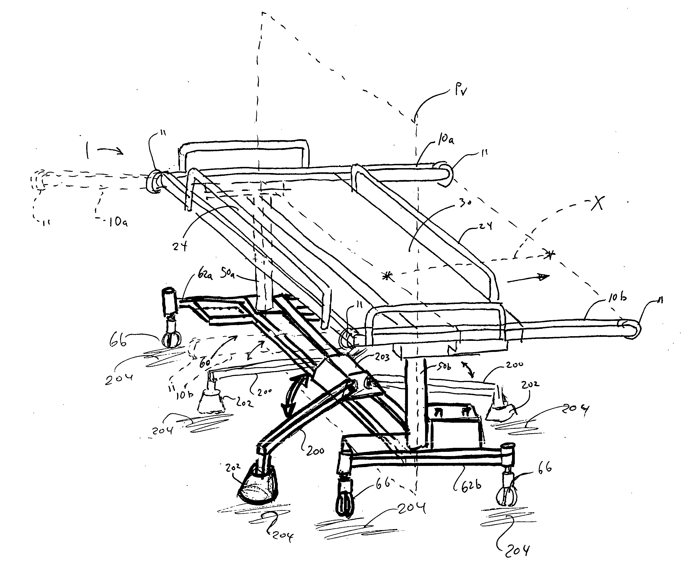
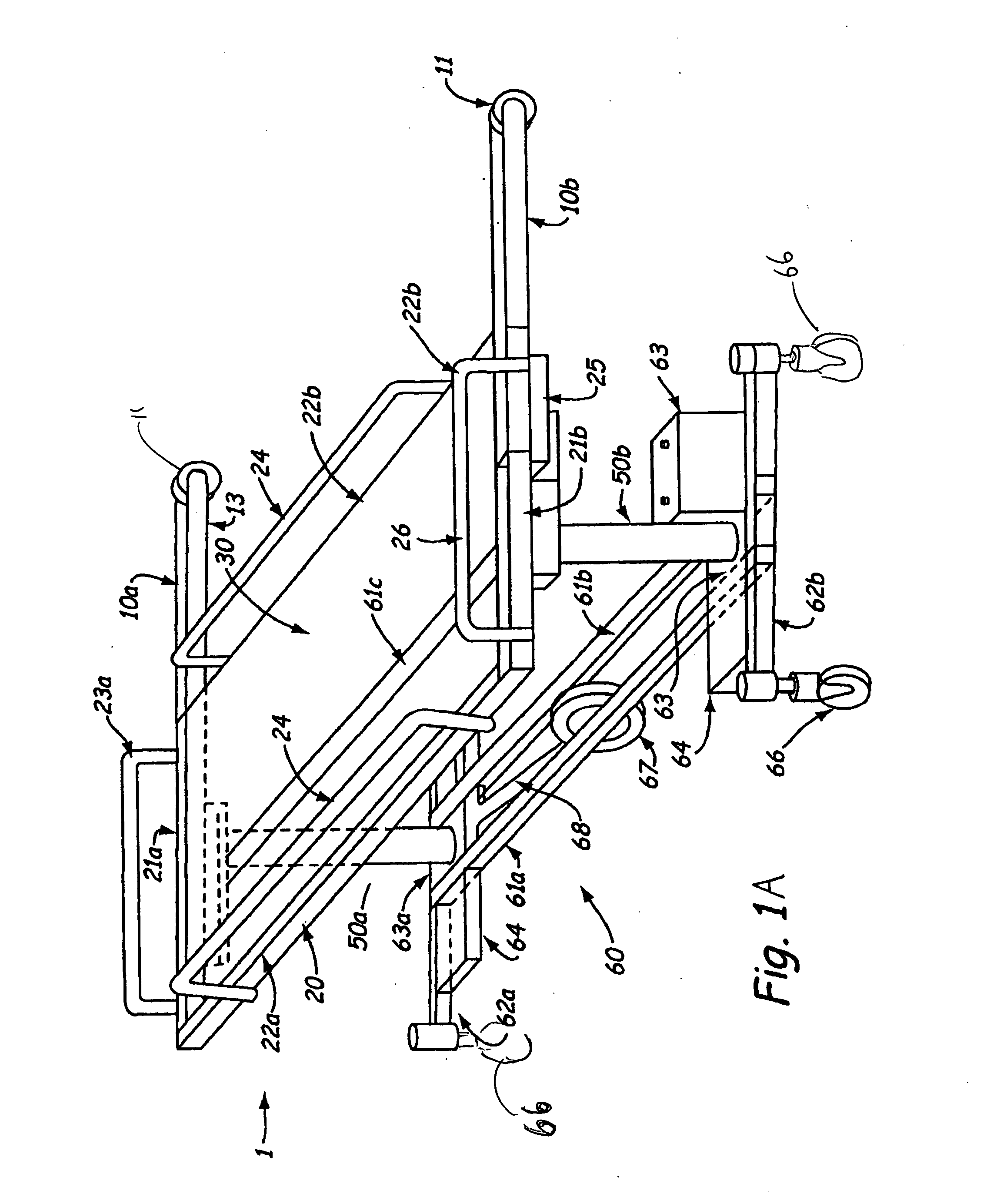
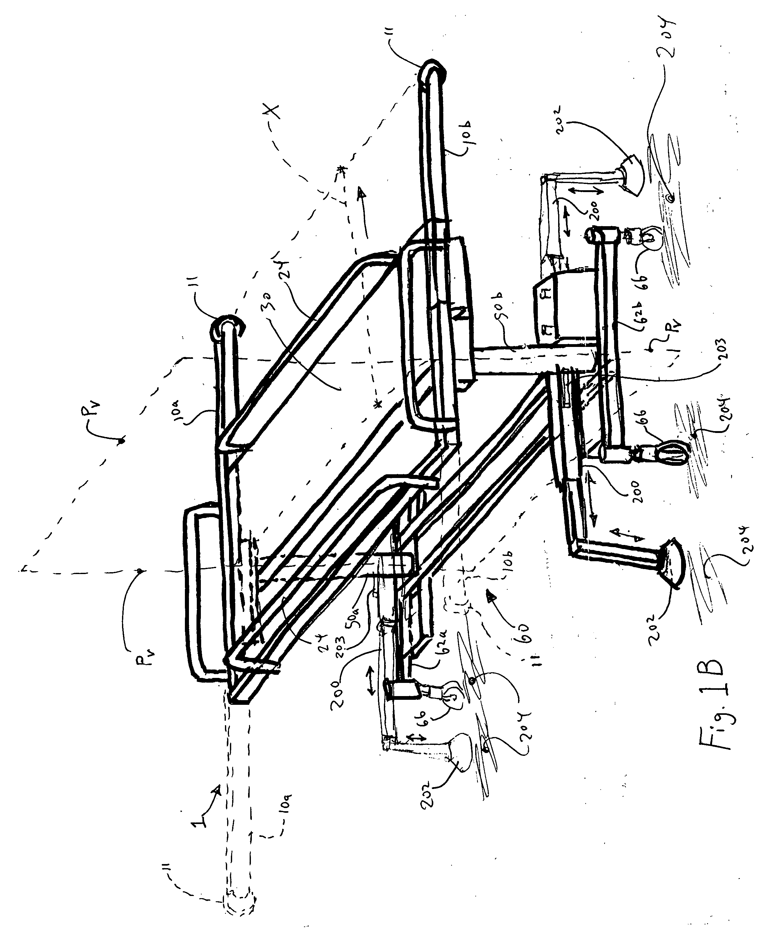
[0034]FIG. 1A is a perspective view of a patient transfer and transport device 1, according to one embodiment of the present invention. As shown in FIG. 1A, the patient transfer and transport device 1 has two transfer arms 10a, 10b, a platform-receiving frame 20, a transfer platform 30, two support posts 50a, 50b, and a base 60. The base 60 and the support posts 50a, 50b support the frame 20 at a desirable height. The transfer arms 10a, 10b are attached to the frame 20 and support the transfer platform 30 during lateral motion away from the frame 20.

[0035] As further shown in FIG. 1A, the platform-receiving frame 20 has a first end 21a, a second end 21b, an enclosed side 22a, and an open side 22b. In one embodiment, the ends 21a, 21b are slotted-sleeve channels, as further explained below. A rail handle 23a is mounted on the first end 21a. A throttle rail handle 23b is mounted on the second end 21b. One of each of the transfer arms 10a, 10b is slidably mounted within each end 21a, ...


PUM


Abstract

The present invention is a transfer and transport device and method for moving a patient from a bed to another location within a medical facility. The transport device includes an integral transfer mechanism for transferring a patient from a hospital bed to the device and back.

Description

CROSS REFERENCE TO RELATED APPLICATIONS [0001] The present application is a continuation-in-part (“CIP”) patent application of U.S. patent application Ser. No. 11 / 017,974 (“the '974 application), which was filed Dec. 21, 2004 and issued on ______ as U.S. Pat. No. ______. The '974 application is continuation patent application of U.S. patent application Ser. No. 10 / 369,210 (“the 210 application”), which was filed Feb. 18, 2003 and issued Feb. 15, 2005 as U.S. Pat. No. 6,854,137. The '210 application claims the benefit under 35 U.S.C. § 119(e) to U.S. provisional application 60 / 357,911, which was filed Feb. 18, 2002 and entitled “Patient Transfer and Transport Device.” All of the aforementioned patent applications are incorporated by reference into the present application in their entireties.FIELD OF THE INVENTION [0002] The present invention relates to apparatus and methods of transporting patients in a medical facility. More particularly, the present invention relates to apparatus a...

Claims


Application Information

Patent Timeline
IPC IPC(8): A61G7/10
CPCA61G7/08A61G7/1019A61G7/1032A61G7/1034A61G7/1046A61G7/1048A61G7/1057A61G7/1065A61G7/1067A61G2007/0528A61G2200/32A61G7/0528
Inventor JOHNSON, DANIEL T.
Owner DANE INDS
Why Eureka
Try Eureka